Automotive
Automotive rear fill “surround sound” with Boss DD-3
Lately I’ve been experimenting with rear fill in my car. Similar to matrix “surround sound”, but not a discrete multichannel system where sounds are meant to originate from the sides or rear; rear fill is intended to improve the front soundstage in a car which is normally pretty poor due to proximity to the left and right speakers as well as cabin reflections. Specifically this is implemented as a delayed, bandwidth limited, mono L-R difference signal for the rear speakers.
There is quite a bit of variance in implementation of this method, such as amount of delay, filter corner frequencies and Q, etc. After spending much time reading and not being confident picking some values, I decided to build a fully variable test setup.
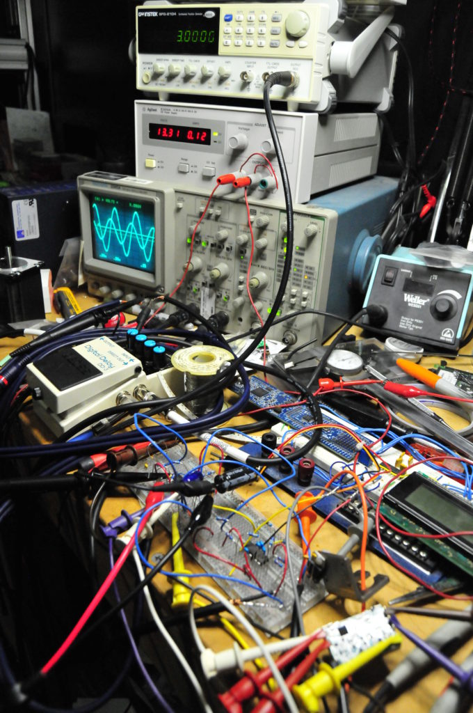
Breadboard and bench test so I don’t burn up my stereo/amps, also verifying proper operation from the DD-3.
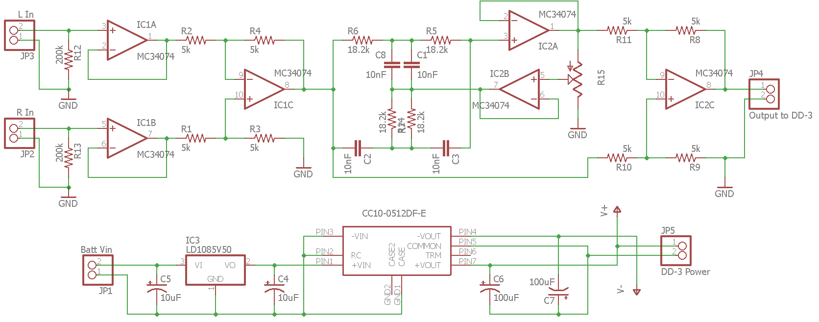
To handle bandpass filtering and create a mono L-R difference signal I started with two op-amps to first buffer the left and right signals and then another op-amp follows as a differential amplifier to create the mono difference signal. This signal is then fed to a twin T cell notch filter with constant in-band gain but adjustable Q to provide variable bandwidth around a center frequency I chose, about 925Hz. The bandwidth of the filter is adjusted by feedback through a potentiometer without affecting gain so relative cutoff frequencies can be changed in real time. To turn the notch filter into a bandpass filter the output of the notch filter is compared to the input by a difference amplifier.
Probably the most important part of this is adding a delay. The effect relies on psychoacoustics to trick your brain into thinking you are in a bigger space since all reflections in a car are early reflections. Due to the speed of sound there just isn’t time in a car to produce late reflections which give your brain a sense of “space”. These reflections are different from echoes which the brain interprets as a separate event. The Haas effect (or precedence effect) defines that if a sound and its reflection arrive at the listener within a sufficiently short period of time the listener will perceive them as the same event. The period of time is different for different sounds, but is generally accepted to be between 20 and 30 milliseconds. The goal with rear fill is to add enough delay to simulate a larger room with later reflections but not produce an echo.
I bought a Boss DD-3 digital delay guitar pedal for this because it is perfect for the test. You can isolate just the delay signal, the delay is continuously adjustable, and one of the adjustment ranges is 12.5-50mS (which is something the MiniDSP and PT2399 can’t do). It has defeatable feedback so there will be no echo and it is digital so the signal should be accurately reproduced. It can also be instantly bypassed with the footswitch which is essential in identifying whether a change is better or worse.
› Continue reading
Spring tester / weight scale
This is another one I finished a couple months ago but haven’t posted. I wanted to test the rate of the springs in the coilover kit on my car, and manufacturers treat this like it’s some kind of trade secret. Except for a few; my kit was from Bilstein who gave me the rates but they weren’t very believable. I knew they were higher than what I was told.
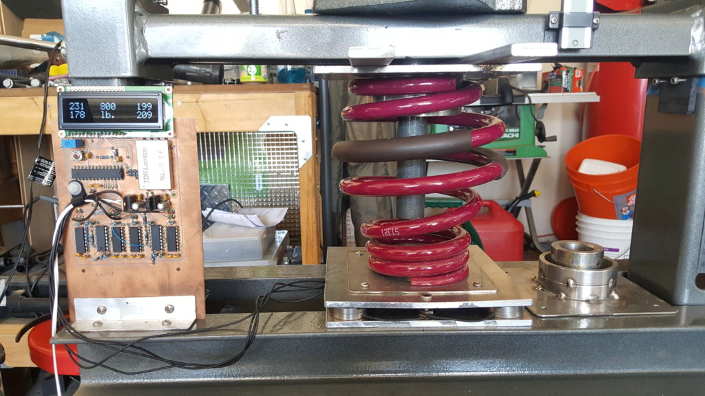
So I built a spring tester. It is basically a weigh scale that can go up to 1000 pounds or so, with a way to safely compress the spring and measure displacement. For the scale I used four load cells with one at each corner of a 1/4″ aluminum plate and another 1/4″ plate to distribute the load to the four load cells and allow fixtures for various springs. The electronics for the load cells are INA103s and some more op-amps for gain. Since load cells are bridge devices a TDK DC-DC converter drives the in-amp rails with +/- 12V. The signal from the in-amps is offset and fed to an ATmega8 which does ADC and puts the values on an LCD. I am displaying the values for each load cell as well as the sum so I can see if any load cells are not being loaded equally which could result in an overload. There is also a button on an interrupt that allows zeroing the summed weight output. › Continue reading
Ducati 749/999 Tail Light
I finished this project a while ago, but never documented it. This is a taillight I made for my 749 before I sold it. I currently have a 999 so maybe I will make another one someday, but the 999 rarely changes out of it’s track/race clothes.
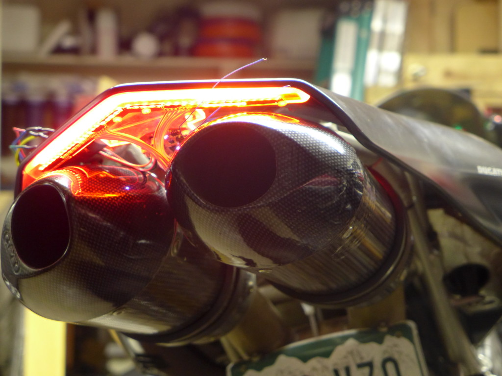
I was doing a lot of street riding when I made this, so I wanted something with better visibility than the (IMO) poor aftermarket replacement taillights. Specifically I was wanting to add a few high brightness pulses when the brake lights were turned on, but with a high enough frequency it would barely be noticeable. It catches your attention but isn’t really that obvious if you weren’t looking right at it. I’ve noticed recently that some fire trucks do this.
I’ve also been interested in a tail light with a light sensor so that the brightness can be ramped up during day time. Motorcycles need all the visibility they can get, but if the tail light gets too bright it will have the opposite effect at night and reduce visibility for people behind you. › Continue reading
Instruments for the GSXR
Since the GSXR is now a street fighter the factory gauges won’t do, and I wanted something I could log air/fuel ratios with so I can jet the bike. I went a little overboard making a new dash.
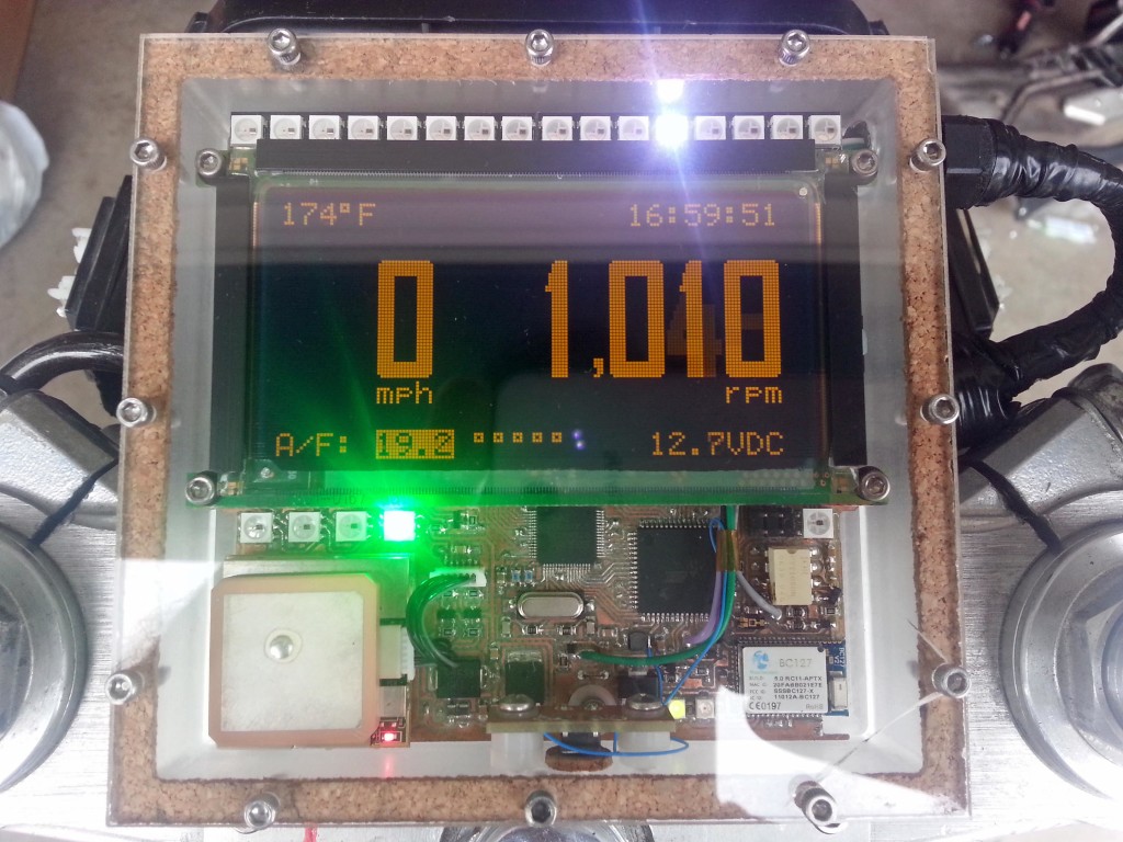
I had a Planar 160×80 EL graphic display that’s been in my parts bin for years that I’ve always wanted to use, and this was perfect. Unfortunately it doesn’t have a controller so I had to interface it to the CPU with an Epson S1D13700 graphic controller. The display indicates speed from a GPS module, air/fuel ratios from the wideband O2 sensor, engine temp, battery voltage, time from GPS, and RPM. I used a light sensor to sense ambient brightness levels and dim the display by changing TC/R in the graphics controller. The refresh of the display is high enough to allow a large dimming range without flickering. The EL display can be refreshed at up to 240Hz. The light sensor also controls the brightness of the bar graph and indicator LEDs. A BC127 bluetooth module allows datalogging via SPP, and I might eventually get around to displaying SMS messages from my phone on the display which was one of the design goals but isn’t done yet.
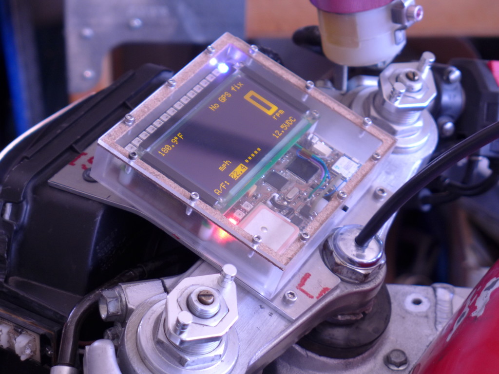
An IR optoisolator senses RPM pulses from the magnetic pickup and protects the system from ignition noise. Addressable LEDs function as indicator lights as well as forming the bar graph at the top of the display. The bar graph can display RPM, battery voltage, engine temp, or A/F ratios depending on the current mode which is selected by a button on the side of the housing. The bar graph is also a two stage shift light which overrides any display mode and goes to full brightness with two different colors to indicate high RPM for shifting. A highlight box on the graphics layer shows which mode is currently active and the graphic and text layers are XOR’ed. I also made a custom bitmapped font I thought went well with the display size and the amount of characters.
› Continue reading
Light pipe tail light for the GSXR
I wanted the new subframe and tail of my GSXR to be really different, I wanted a kind of rough raw look but still really clean. I used unfinished stainless steel and some really angular sections to achieve this. One of the most important parts about how I built the tail was being able to add a light pipe around the outside perimeter for a taillight.
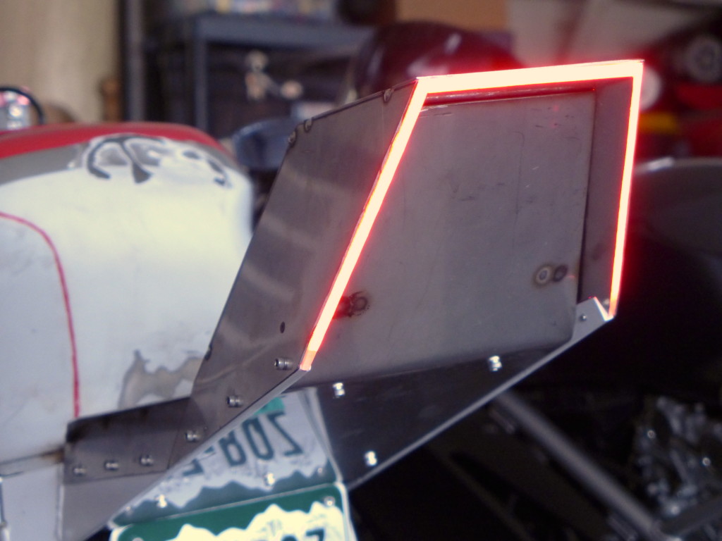
I made the light pipe from 1/4″ acrylic, cut out three sections and used acrylic cement to join them. I added LEDs and coupled them to the light guide with LOCA glue. The amount of LEDs I had to use to achieve good brightness meant I would need to build a boost power supply for the LED drivers since the strings would require more than the available voltage. Here is a simple boost power supply I made with three LED drivers and an ATtiny2313 for controlling flashing the side segments as turn signals. There was some logic required to sense the turn signal state prior to the switch and keep the sides working correctly as both brake and signals.
› Continue reading
ELM327 emulator
I’ve been wanting to get diagnostic data from my truck for quite a while, but I haven’t wanted to spend the big bucks on the tools. Recently though I came across the ELM327. It’s an all-in-one IC solution for a scan tool. It even has a UART. You just need a few external parts for different COM interfaces and an OBDII connector. However, the IC itself is $32.50, and you still have to source the OBDII connector, create the schematic, do the layout, make the board, etc. So I decided to try one of the “ELM327 based” products off eBay. It was $20 shipped from Hong Kong, and already has a USB interface.

The product is based on a PIC18, with an FTDI FT232R serial to USB converter. Use FTDI’s driver when you connect it to your PC though. I used the driver included on the CD that came with the tool, and it enumerated as a “high speed USB serial UART” and wouldn’t communicate. I had to use FTDI’s driver removal tool to get rid of it so I could reinstall the correct one.
I tried the device on my truck with a couple different software programs: ScanTool.net, OBD2Spy, and wOBD. However the results were underwhelming, as I got two different sets of codes with the first two and the last program wouldn’t communicate with the tool. ScanTool.net reported P0403, P0405, and P0460. OBD2Spy gave me P0204, P0304, and P0500. Obviously that’s not very helpful.
So I opened up the ELM327 datasheet and Realterm. Realterm is always my favorite terminal program, but in this case I had to switch to Hyperterminal since Realterm doesn’t have the “Append line feeds to incoming line ends” feature. Realterm overwrites everything from the device on the same line.
I started with a simple protocol test, to make sure everything is working. Then I tried pulling PID 05, which is coolant temperature. It responded with the proper value. So I moved on to checking the number of codes. There were two. Finally I pulled those codes. They turned out to be P0204, P0304, and P0500. I’m not sure why the ECU thought there was two codes but listed three. Anyway, OBD2Spy gets the nod here. If you look at the output you can see that the other program was off by one byte, which is why the codes are similar but incorrect.
So the emulator works as advertised, at least in this test. The next problem though is that there are only a handful of previously defined PIDs that auto manufacturers use so that they can get diagnostic tool companies to pay for the extended PIDs required to actually do any useful troubleshooting. In order to get real-time data of detailed systems, you have to pay for software that has the extended PIDs.
Forza 3 multiscreen setup
I recently put together a multiscreen setup of Forza 3 motorsports for Xbox 360. Forza 3 is the first driving game I’ve played that made spending the time and money worth it. However, I had a few annoying problems along the way so I’m writing this article to potentially help anyone with problems like I had. This isn’t about how to use multiscreen to increase the field of view on one monitor (which is about all you can find on the web). It’s about using three screens together for one wide display with Forza 3. At the end I share how I did all this for cheap.

First off, you need three of the SAME copies of Forza 3. Mixing in an ultimate collection with the regular versions won’t work, they won’t connect. It took me a while to figure this out. Either use three ultimate collection versions or three regular versions. If you have three regular copies and you bought the ultimate to get more cars, you don’t need to go out and buy two more UC copies. Just put the UC disc in each machine and install disc 2. Then put the regular copies back in.
Second, you need a switch. I read somewhere on forzamotorsport.net that the data sent between the three Xboxes is a large amount of minimum frame size packets so a hub will work but you run the risk of dropping packets which will cause lag. Remember a hub and a switch do the same thing but a switch can learn where packets need to go based on their address, and a hub always just broadcasts to all stations. That is, a switch is more efficient. Use the uplink port of the switch that connects the three Xboxes to connect to your wireless router or gateway (internet).
Then you will need to verify the connection between the three Xboxes. There are a lot of people on the web saying that you need to be connected to Xbox Live, you need a Gold subscription to Xbox Live for each console, etc. None of this is true. You don’t need Xbox live for this to work. I know because I tested the multiscreen capabilities before I signed any of my consoles on to Xbox live. In fact I probably wouldn’t have bothered with Xbox live but I wanted the LFA from Stig’s Garage car pack.
Anyway, sign in on the Xbox that will be your center station, it will be the host and have your profile. It is easiest to test your connection by connecting to Xbox live through the test network utility in the console settings. If you go to: my Xbox / console settings / network / test settings it will test the connection from the console all the way through the local network to Xbox live. If you feel like it you can log on to your router and assign a static address to the three Xboxes to keep it tidy. You can see what IP each of your consoles was assigned by the router in the network settings on the console. All that matters is that they are different and in a range accessible to your router. None of that is really necessary though, if you only have a switch connecting the three consoles. The Xboxes will each assign themselves an address if they can’t find a DHCP server like your router. Your router is typically what assigns local IP addresses. › Continue reading
Fast idle mod
I found this write up by Skweeker at powerstroke.org for adding a fast idle or high idle switch to your pre-’05 6.0l. It takes advantage of the PTO capability that is programmed into the engine computer, even if you don’t have a PTO. Takes only a few minutes, and works great. Note that this write-up is specifically for 2004 with automatic.
“Here’s what you need to do. Look up under the dash between the steering column and the parking brake pedal. You will find a wiring harness behind the parking brake handle with a bunch of wires coming out of the harness that have the ends sealed off with charcoal?? colored heat shrink tubing.
If your not sure what you are looking at, look at the three wiring harnesses that come through the firewall to the left of the steering column shaft into the passenger compartment. The top harness is big, the middle harness is smaller than the top harness and the last harness closest to the floor is smaller still. The wire you are looking for comes out of the the middle harness where the harness routes up to the dash directly behind the parking brake handle.
One of these wires will be Light Blue with a Yellow stripe. This is the PTO function wire from the PCM. Placing battery power (battery positive) on this wire will command the PCM to raise the idle speed to 1200rpm as long as the transmission is in Park or Neutral and the service brake is released, meaning your foot is not on the brake pedal and the brake lights are not activated.
The other wire you are looking for is a White wire with a Light Blue stripe. This one is also easy to find. While looking under the dash direct your attention to the black OBD II datalink connector mounted to the lower part of the dash to the right of the steering column. This connector is what a service tech uses to hook up a scan tool which is needed to communicate with the vehicle PCM in order to check engine sensor data, engine trouble codes and to REFLASH your PCM. (You’ve heard about FLASHES haven’t you???)
Anyway, look at this black connector and follow the wiring harness from the plug back up and inside the dash. Along the harness not too far up from the plug you will find the White wire with a Light Blue stripe included in the bundle of wires but the wire just stops short of the connector. Yes the wire does not plug into any one of the ports of the datalink connector.
This White wire with a Light Blue stipe is your positive battery source wire that you will connect to the Light Blue with a Yellow stripe PTO wire through a switch.”
I installed a rocker switch on the panel just below and to the right of the headlight switch. The plastic is really soft, so it cuts easily with a hobby knife. Plus, the fuse panel drops out right underneath which makes wiring everything up really easy.
How much electric current does a truck really use?
So, a while back my truck was getting slow to start. I checked the battery voltage with the truck running, and it was only 11 volts or something. I started the troubleshooting process by replacing the alternator with one from the local parts store, but it didn’t fix the problem. I changed both batteries. Still didn’t fix the problem. So I did some diagnostics with an ammeter and a voltmeter and figured out that my brand-new alternator was bad. I took it back to the parts store, where they gave me another one. I had them test it, and it failed on their bench tester. So did the next one. They finally gave me my money back and I bought one from Ford. It worked just fine.
While I was looking for alternators, I found some high output models. This sounds cool, but do you really need it? I pull a trailer pretty regularly, and I imagined that the trailer lights and brakes would be a pretty good additional load on the electrical system. I had also read that people buying these “high output” alternators had been disappointed with their actual output, so I thought it might be good to find out.
I wasn’t sure how dirty the output of the alternator would be, or how quickly the output might fluctuate which ruled out the use of an inductive current clamp. So I looked around and found a hall-effect current sensor from Allegro Microsystems. The manufacturer’s part number is ACS758KCB-150B-PFF-T. This sensor has a maximum current rating of 150 Amps, and outputs a linear 0-5V signal proportional to the current that passes through the device. It’s fast enough to record transients and will faithfully reproduce both AC and DC currents. The output of the sensor was fed to an Atmel ATMega8, which did ADC duties and sent the data out it’s UART to a MAX232 level converter. I just picked up the data stream with hyperterminal on my laptop. Excel let me manipulate the raw data and make some pretty graphs. I made the circuit with my CNC machine. Here’s what it looks like.

The output of the alternator was alot cleaner than I had expected. I thought there would be more of a rectified three phase look due to the phases generated inside the alternator. This picture of the scope shows the trace of the output of the sensor at idle.

Here is a graph of the data from an engine start up. The Y-axis values are actual current draw in Amps. Time is shown on the X-axis, but the numbers represent the conversion events of the ADC, which happen at approximately 15Hz. This equates to about 40 seconds. The noise is real as far as I can tell. I didn’t use a ground plane, but the trace from the sensor output to the Mega’s ADC input is only about a quarter of an inch. I added a large filter capacitor to the sensor’s output and the waveform didn’t change at all. *edit: I messed that up though, I wasn’t paying attention to where I put it.*

Then I took the truck for about a ten minute drive. I had the lights on, but not the radio or anything extra.

It’s interesting to note how much power the transmission consumes when it’s in gear. The first plot is idling in park, the second plot again shows the truck idling in park at the end of the plot. It’s a clear 20 Amp drop from when the truck was in drive.
I hooked up my horse trailer, but even with all the lights on and everything it only shifted the curve up 10 Amps. The trailer brakes (which I thought would be a significant load) didn’t even show up. I’m still curious about this, as the trailer brake control wiring is usually about 10-12 guage, which is almost the same gauge wire the alternator output has to connect it to the battery. Why bother to wire trailer brake wiring with wire that has an ampacity of 100 Amps or so if it only uses a few amps? There must be more to the story.
Here is the schematic. Sorry it’s not all labelled but I didn’t expect to be posting it at the time. Click on the image to view full size. Capacitors C1 and C2 are for the crystal, 22pF. Capacitors C3-C10 are decoupling capacitors or buffers for the power supply. C11-C14 are typically 1uF. Check the component datasheets for your application.
** I keep getting requests for values, so here is some more detail. The oscillator value is not important, I probably used 8MHz. This circuit doesn’t need high speed. C3 and C4 are decoupling capacitors, usually 0.1uF. C5 and C6 are not necessary, I just added them for flexibility since it was a prototype board. All you need there is C15 which is a bulk capacitor for the voltage regulator. I can’t remember what C7 is, it’s in the AVR datasheet. C9 and C10 aren’t necessary, I was trying to implement a low pass filter but it’s incorrect. All C9 and C10 will do is cause the sensor to drive the output harder. I needed an RC filter but only got the C. That should cover it.

And here’s the layout.

I neglected to add a header for ISP. I was in a hurry to get it done and forgot. The target supply voltage in this application is 11-14V, but supply voltage could be extended to +45V with the appropriate version of the 7805.
Here’s the source code for the Mega8. Compiles with AVR Studio and AVR GCC. It’s a timer-driven interrupt, that starts an ADC conversion of the sensor output and then sends the result to the UART. It uses standard 9600 8N1. The result is left-adjusted so it’s only 8 bit. If you don’t need both positive and negative current measurements, then it would be best to remove the offset of the sensor and use the internal 2.5V ADC reference for better accuracy. The decimal to BCD routine at the end is something I figured out so I can just do a file capture in hyperterminal and import it directly into Excel. › Continue reading
12 Volts on the trailer without a truck
Ever wanted to run the 12 volt stuff on your horse trailer or camper without the truck hooked up and running? I wanted to be able to run the 12 volt lighting in the back of my horse trailer and the water pump without draining the batteries on the truck or leaving it running all the time. The truck’s electrical system isn’t really designed for large charge/discharge cycles, so it’s best to keep the batteries charged. If you’re plugged in to AC power though, you can run your 12 volt stuff without a truck if you add a power supply.
I found a cheap 12 volt power supply from allelectronics that is actually a converted PC power supply. Allelectronics has all kinds of surplus electronic stuff, so you can probably find something that will work. Otherwise, you can buy a PC power supply anywhere and convert it yourself. The only other thing you need is a high-current diode to prevent the power supply sinking current when the truck is plugged in. Since the power supply puts out 12 volts and a properly operating automotive electrical system puts out 13-14 volts, having both operating at the same time isn’t a problem as long as you use the diode. If the truck is plugged in while the power supply is operating, the truck will supply current and the diode will be reverse-biased until the voltage drops below 12 volts, and then the diode will forward-bias and the power supply will take over. Make sure to fuse the output of your power supply to the 12 volt bus. Connect the output of the power supply to a fuse, and then the other side of the fuse to the anode of the diode (usually the non-stripe end. check the datasheet). Connect the cathode of the diode (stripe end) to the 12 volt bus.
The only problem you may have is that you will have to convert any strings of high-current 1156 and similar light bulbs to LED or the power supply will “protect” itself by shutting off when it sees the low and slowly rising resistance of the bulbs. Mine works fine with the single bulb of the porch light and fine with the motor of the water pump but dies when I turn on the bank of three bulbs in the back. I haven’t changed them to LED yet.
Other Stuff
Recent Posts
- 6CY7 dual triode valve amplifier
- Air quality sensor (TVOC and eqCO2)
- Automotive rear fill “surround sound” with Boss DD-3
- Spring tester / weight scale
- Ducati 749/999 Tail Light
- Instruments for the GSXR
- Light pipe tail light for the GSXR
- M17x 6990m / 6970m overheating
- PAR / Spectrum analyzer
- Acrylic polishing and scratch removal
Archives
- May 2019 (2)
- April 2017 (3)
- October 2015 (1)
- May 2015 (1)
- March 2014 (2)
- December 2013 (1)
- July 2013 (1)
- November 2012 (1)
- October 2012 (4)
- September 2012 (1)
- August 2012 (3)
- June 2012 (1)
- March 2012 (1)
- February 2012 (1)
- January 2012 (1)
- October 2011 (3)
- July 2011 (1)
- June 2011 (3)
- May 2011 (2)
- April 2011 (1)
- December 2010 (1)
- August 2010 (1)
- July 2010 (3)
- April 2010 (2)
- March 2010 (2)
- January 2010 (2)
- December 2009 (2)
- October 2009 (2)
- September 2009 (1)
- August 2009 (15)