Powerstroke
Turn signals for a trailer
I’ve been working intermittently on a project to come up with a way to add turn signals to the side of a trailer without needing any extra wiring from the truck. The way people normally do this is by tapping the side markers into the turn signal wires. However, that makes the side markers turn on and off with the brakes which makes for a confusing signal. There is no shortage of patents for adding this type of capability, but they usually require a unique transmitter aboard the truck that communicates with another unique receiver on the trailer. Since the 6 pin standard is ubiquitous, that type of system will likely not be available or popular for some time. I didn’t want to add any special hardware to the truck either. So I’ve been working on a solution that taps into the trailer’s main electrical harness and creates an extra side turn signal for each side of the trailer and also functions as a clearance light.
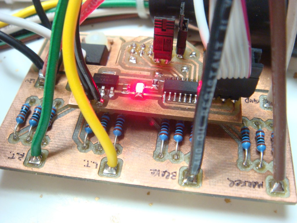
You can use any standard clearance light and it will function as a clearance light when the lights are on, and also flash that light when the appropriate turn signal is on. The brakes will not cause the side markers to flash. You can add new lights, or simply intercept the wiring to existing clearance lights. The only modification is to the trailer, and it will work the same for any truck. The only requirement is that the trailer has electric brakes and the truck has a brake controller.
My code is running on an ATtiny24, on a board I prototyped just for this. I built an in-line harness for testing that passes the signals from the 6 pin connector to the trailer, but taps into those signals for the logic. My device has two standard LED clearance lamps attached as left and right turn signals for testing. This system is an add-on to the existing trailer wiring, so in the event of a failure nothing is compromised.
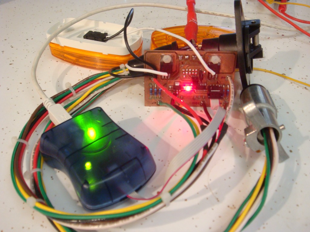
It has been tough getting this working, as there’s not exactly a manual for how the truck and the brake controller handle the signals. It’s taken a few months, as evidenced by the tarnished PCB. If I remember right I made it this summer.
Fast idle mod
I found this write up by Skweeker at powerstroke.org for adding a fast idle or high idle switch to your pre-’05 6.0l. It takes advantage of the PTO capability that is programmed into the engine computer, even if you don’t have a PTO. Takes only a few minutes, and works great. Note that this write-up is specifically for 2004 with automatic.
“Here’s what you need to do. Look up under the dash between the steering column and the parking brake pedal. You will find a wiring harness behind the parking brake handle with a bunch of wires coming out of the harness that have the ends sealed off with charcoal?? colored heat shrink tubing.
If your not sure what you are looking at, look at the three wiring harnesses that come through the firewall to the left of the steering column shaft into the passenger compartment. The top harness is big, the middle harness is smaller than the top harness and the last harness closest to the floor is smaller still. The wire you are looking for comes out of the the middle harness where the harness routes up to the dash directly behind the parking brake handle.
One of these wires will be Light Blue with a Yellow stripe. This is the PTO function wire from the PCM. Placing battery power (battery positive) on this wire will command the PCM to raise the idle speed to 1200rpm as long as the transmission is in Park or Neutral and the service brake is released, meaning your foot is not on the brake pedal and the brake lights are not activated.
The other wire you are looking for is a White wire with a Light Blue stripe. This one is also easy to find. While looking under the dash direct your attention to the black OBD II datalink connector mounted to the lower part of the dash to the right of the steering column. This connector is what a service tech uses to hook up a scan tool which is needed to communicate with the vehicle PCM in order to check engine sensor data, engine trouble codes and to REFLASH your PCM. (You’ve heard about FLASHES haven’t you???)
Anyway, look at this black connector and follow the wiring harness from the plug back up and inside the dash. Along the harness not too far up from the plug you will find the White wire with a Light Blue stripe included in the bundle of wires but the wire just stops short of the connector. Yes the wire does not plug into any one of the ports of the datalink connector.
This White wire with a Light Blue stipe is your positive battery source wire that you will connect to the Light Blue with a Yellow stripe PTO wire through a switch.”
I installed a rocker switch on the panel just below and to the right of the headlight switch. The plastic is really soft, so it cuts easily with a hobby knife. Plus, the fuse panel drops out right underneath which makes wiring everything up really easy.
How much electric current does a truck really use?
So, a while back my truck was getting slow to start. I checked the battery voltage with the truck running, and it was only 11 volts or something. I started the troubleshooting process by replacing the alternator with one from the local parts store, but it didn’t fix the problem. I changed both batteries. Still didn’t fix the problem. So I did some diagnostics with an ammeter and a voltmeter and figured out that my brand-new alternator was bad. I took it back to the parts store, where they gave me another one. I had them test it, and it failed on their bench tester. So did the next one. They finally gave me my money back and I bought one from Ford. It worked just fine.
While I was looking for alternators, I found some high output models. This sounds cool, but do you really need it? I pull a trailer pretty regularly, and I imagined that the trailer lights and brakes would be a pretty good additional load on the electrical system. I had also read that people buying these “high output” alternators had been disappointed with their actual output, so I thought it might be good to find out.
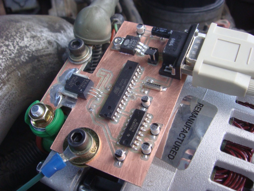
I wasn’t sure how dirty the output of the alternator would be, or how quickly the output might fluctuate which ruled out the use of an inductive current clamp. So I looked around and found a hall-effect current sensor from Allegro Microsystems. The manufacturer’s part number is ACS758KCB-150B-PFF-T. This sensor has a maximum current rating of 150 Amps, and outputs a linear 0-5V signal proportional to the current that passes through the device. It’s fast enough to record transients and will faithfully reproduce both AC and DC currents. The output of the sensor was fed to an Atmel ATMega8, which did ADC duties and sent the data out it’s UART to a MAX232 level converter. I just picked up the data stream with hyperterminal on my laptop. Excel let me manipulate the raw data and make some pretty graphs. I made the circuit with my CNC machine. Here’s what it looks like.
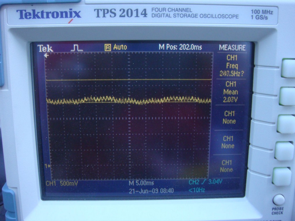
The output of the alternator was alot cleaner than I had expected. I thought there would be more of a rectified three phase look due to the phases generated inside the alternator. This picture of the scope shows the trace of the output of the sensor at idle.
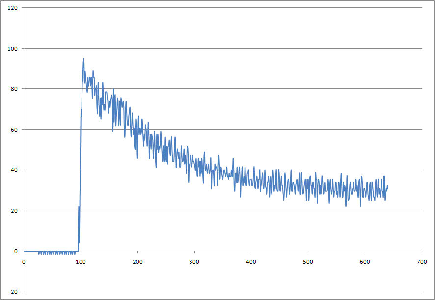
Here is a graph of the data from an engine start up. The Y-axis values are actual current draw in Amps. Time is shown on the X-axis, but the numbers represent the conversion events of the ADC, which happen at approximately 15Hz. This equates to about 40 seconds. The noise is real as far as I can tell. I didn’t use a ground plane, but the trace from the sensor output to the Mega’s ADC input is only about a quarter of an inch. I added a large filter capacitor to the sensor’s output and the waveform didn’t change at all. *edit: I messed that up though, I wasn’t paying attention to where I put it.*
Then I took the truck for about a ten minute drive. I had the lights on, but not the radio or anything extra.
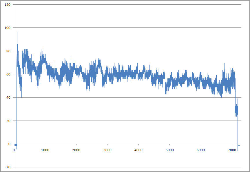
It’s interesting to note how much power the transmission consumes when it’s in gear. The first plot is idling in park, the second plot again shows the truck idling in park at the end of the plot. It’s a clear 20 Amp drop from when the truck was in drive.
I hooked up my horse trailer, but even with all the lights on and everything it only shifted the curve up 10 Amps. The trailer brakes (which I thought would be a significant load) didn’t even show up. I’m still curious about this, as the trailer brake control wiring is usually about 10-12 guage, which is almost the same gauge wire the alternator output has to connect it to the battery. Why bother to wire trailer brake wiring with wire that has an ampacity of 100 Amps or so if it only uses a few amps? There must be more to the story.
Here is the schematic. Sorry it’s not all labelled but I didn’t expect to be posting it at the time. Click on the image to view full size. Capacitors C1 and C2 are for the crystal, 22pF. Capacitors C3-C10 are decoupling capacitors or buffers for the power supply. C11-C14 are typically 1uF. Check the component datasheets for your application.
** I keep getting requests for values, so here is some more detail. The oscillator value is not important, I probably used 8MHz. This circuit doesn’t need high speed. C3 and C4 are decoupling capacitors, usually 0.1uF. C5 and C6 are not necessary, I just added them for flexibility since it was a prototype board. All you need there is C15 which is a bulk capacitor for the voltage regulator. I can’t remember what C7 is, it’s in the AVR datasheet. C9 and C10 aren’t necessary, I was trying to implement a low pass filter but it’s incorrect. All C9 and C10 will do is cause the sensor to drive the output harder. I needed an RC filter but only got the C. That should cover it.
And here’s the layout.
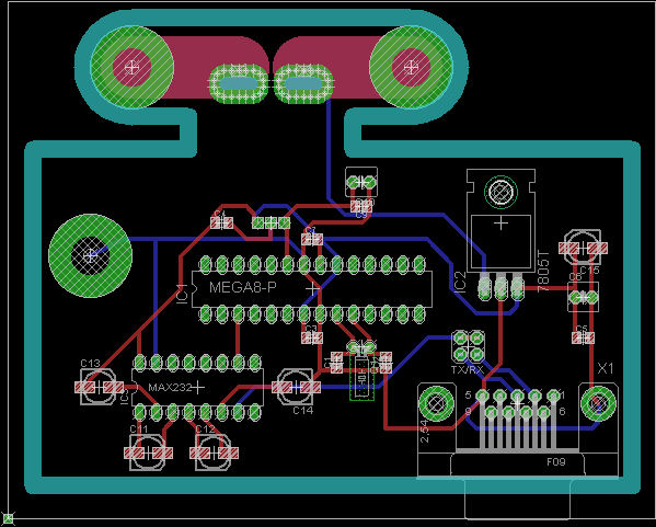
I neglected to add a header for ISP. I was in a hurry to get it done and forgot. The target supply voltage in this application is 11-14V, but supply voltage could be extended to +45V with the appropriate version of the 7805.
Here’s the source code for the Mega8. Compiles with AVR Studio and AVR GCC. It’s a timer-driven interrupt, that starts an ADC conversion of the sensor output and then sends the result to the UART. It uses standard 9600 8N1. The result is left-adjusted so it’s only 8 bit. If you don’t need both positive and negative current measurements, then it would be best to remove the offset of the sensor and use the internal 2.5V ADC reference for better accuracy. The decimal to BCD routine at the end is something I figured out so I can just do a file capture in hyperterminal and import it directly into Excel. › Continue reading
Diesel, sulfur, NOx, and EGR
I’ve heard alot of people complaining about the exhaust gas recirculation (EGR) system on Ford’s 6.0L Power Stroke engine. One in particular comes to mind, from a “conversation” I had with FK000@aol.com over at thedieselstop.com: “Is it really necc. to cool the EGR with hot coolant… NO”. Actually, it’s common in the industry at this point. Just because the coolant is “hot” doesn’t mean that it can’t remove heat from exhaust gas that happens to be anywhere from 2 to 7 times hotter. It’s simple thermodynamics. That same individual went on to describe engineers as incompetent because sometimes things break, and closed the thread so no one could respond.
A little background will show the challenges that have been presented to the auto industry, with cooled EGR being one of the methods developed by automakers to meet increasingly stringent emissions standards. This appeared in Amsoil’s Action News and is a good summary of the saga of diesel emission regulations:
“Diesel engine emissions have been an ongoing environmental concern for the past few decades. Particulates and nitrogen oxides (NOx) associated with health problems and damaging smog and acid rain have been targeted by governments globally, and the United States, Europe and Japan have responded to demands to reduce these harmful emissions. NOx forms when atmospheric nitrogen in the powercylinder oxidizes. Because peak cylinder temperature plays a key role in NOx formation, methods of reducing the temperature, including cooled exhaust gas recirculation (EGR) technology, have been employed in modern diesel engines as solutions to reducing NOx emissions. Diesel particulates are composed of solid carbon (soot), sulfate, bound water and unburned fuel and oil. Because sulfur is key to particulate formation, the sulfur level in diesel fuel has been gradually decreased over the years.
In the U.S., particulate and NOx levels were first regulated in 1988, with regulations becoming increasingly stringent through the years. In fact, 1988 standards set NOx and particulate levels at 14.4 g/kW-hr (grams/kilowatts-hour) and 0.8 g/kW-hr respectively, while 2010 standards have been set at 0.27 g/kW-hr and 0.013 g/kW-hr respectively.
Between the years 1988 and 1991, emission standards were met by improving in-cylinder combustion through the use of unit injectors, electronic controls, controlled air swirl, improved combustion bowl design, reduced piston crevice volume, turbo-charging, air inter-cooling and reductions in oil consumption. The year 1991 also saw the use of high top rings to lower particulate emissions. Fuel sulfur was successfully reduced by 90 percent in order to meet 1994 particulate targets, dropping from 5,000 ppm to 500 ppm in October 1993. The sulfur reduction had no harmful effects on diesel engines, and the API CG-4 oil category was established in 1994 using low-sulfur diesel fuel in all engine tests. By 1998, retarded fuel injection timing was introduced to meet increasingly stringent NOx emission standards. By displacing combustion until later in the expansion stroke, retarded fuel injection timing lowers the peak fl ame temperature and effectively reduces NOx formation. High top rings and retarded fuel injection timing increased soot-loading on the oil, leading to the introduction of API diesel oil category CH-4 in order to prevent viscosity increases and increased wear due to soot. In order to meet 2002 emission standards, most engine manufacturers introduced low levels (10-15%) of cooled EGR technology. EGR engines reduce NOx emissions by recirculating a portion of the exhaust to the engine’s combustion chamber, lowering peak combustion temperature and NOx formation. Although EGR engines effectively reduce emissions, they also run hotter and introduce higher levels of soot and acid into the oil, leading to increased wear, increased oil viscosity and shorter oil drain intervals. The API CI-4 diesel oil specifi cation was introduced in December 2001 to protect against the higher temperatures and increased levels of acids, soot and oxidation associated with EGR engines. API CI-4 oils were formulated with increased detergent levels to protect rings and liners and increased oxidation inhibitors to prevent bearing corrosion. API issued an upgrade to its CI-4 specifi cation, CI-4 PLUS, in September 2004 in order to provide improved oxidation resistance, shear stability, acid neutralization and soot dispersancy for EGR engines. Some manufacturers released their own diesel oil performance specifi cations in order to assure optimum protection for their equipment. For example, Mack released its stringent EO-N Premium Plus High Performance Diesel Engine Oil specifi cation in the spring of 2002 and upgraded it in April 2003 to EO-N Premium Plus 03 and again in June 2006 to EO-O Premium Plus. The latest round of emission standards went into effect in 2007, requiring even more stringent NOx and particulate emissions reductions. While low levels of EGR technology (10-15%) were successfully applied in diesel engines to meet 2002 NOx emissions standards, most manufacturers incorporated increased EGR rates of 25-35% in order to meet 2007 standards. Increased EGR rates mean 2007 and newer diesel engines run hotter than their predecessors, requiring diesel oils meeting the latest API CJ-4 specifi cation to be formulated with improved oxidation resistance properties to prevent thermal runaway and maintain engine protection. Decreasing the level of sulfur in diesel fuel has been determined to be the most cost-effective way to decrease particulate emissions. The introduction of ultra low sulfur diesel (ULSD) fuel in June 2006 dropped diesel fuel sulfur levels from 500 ppm to 15 ppm in order to meet 2007 particulate limits, provide compatibility with NOx after-treatment systems and enable high EGR rates.
In addition, in order to further reduce particulate emissions, diesel particulate filters (DPF’s) were incorporated into all 2007 and newer American diesel engines, and CJ-4 diesel oils are faced with the challenge of balancing engine protection with DPF life. Increased EGR, although effectively decreasing NOx emissions, results in less effi cient combustion and increased levels of soot, and some of it fi nds its way into the engine oil. Detergents within the oil are responsible for preventing soot from accumulating on internal engine components and increasing friction and wear, as well as preventing soot particles from agglomerating into larger particles that increase oil viscosity and clog oil filters.”
Isuzu’s truck products website simply states the benefits of cooled EGR:
“Cooled EGR Adds a cooling device to the EGR path, helping to lower the combustion temperature, further reducing the amount of NOx formation”.
Many studies and experiments on EGR and EGR cooling can be found by searching google.
The real problem with the EGR system on the 6.0L is actually the oil cooler. When the oil cooler clogs up (I’m still investigating why this happens, it’s due to an undetermined particulate in the coolant system) there is not a sufficient flow of coolant to the EGR cooler, and it consequentially overheats. This stresses the fins of the heat exchanger, and they crack allowing coolant to pass into the EGR stream.
Both upgraded EGR coolers and oil coolers are available at BulletProofDiesel which will retain proper emissions functionality while surviving at higher temperatures. I haven’t tested these products personally, but just by looking at it it’s a more robust design than stock. The oil cooler is impressive, it looks like their own design machined from aluminum bar stock, not a modification of the stock unit.
In summary, don’t blame automotive engineers for adding an “unnecessary” device. It was the actions of the EPA and environmentally conscious individuals that created government regulations for using things like EGR. The automotive industry does extensive testing on their products, and it is presumptuous and ignorant to insinuate they are incompetent. Engineering, manufacturing, and estimating the effects of a customer’s actions on your product may be more difficult than you assume.
Other Stuff
Recent Posts
Archives
- May 2019 (2)
- April 2017 (3)
- October 2015 (1)
- May 2015 (1)
- March 2014 (2)
- December 2013 (1)
- July 2013 (1)
- November 2012 (1)
- October 2012 (4)
- September 2012 (1)
- August 2012 (3)
- June 2012 (1)
- March 2012 (1)
- February 2012 (1)
- January 2012 (1)
- October 2011 (3)
- July 2011 (1)
- June 2011 (3)
- May 2011 (2)
- April 2011 (1)
- December 2010 (1)
- August 2010 (1)
- July 2010 (3)
- April 2010 (2)
- March 2010 (2)
- January 2010 (2)
- December 2009 (2)
- October 2009 (2)
- September 2009 (1)
- August 2009 (15)
