AVR
Spring tester / weight scale
This is another one I finished a couple months ago but haven’t posted. I wanted to test the rate of the springs in the coilover kit on my car, and manufacturers treat this like it’s some kind of trade secret. Except for a few; my kit was from Bilstein who gave me the rates but they weren’t very believable. I knew they were higher than what I was told.
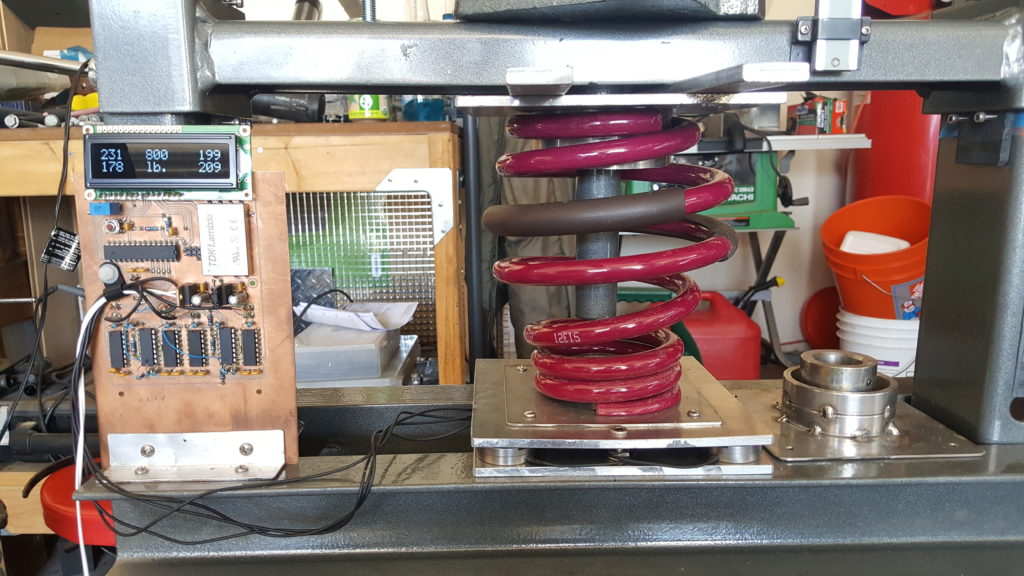
So I built a spring tester. It is basically a weigh scale that can go up to 1000 pounds or so, with a way to safely compress the spring and measure displacement. For the scale I used four load cells with one at each corner of a 1/4″ aluminum plate and another 1/4″ plate to distribute the load to the four load cells and allow fixtures for various springs. The electronics for the load cells are INA103s and some more op-amps for gain. Since load cells are bridge devices a TDK DC-DC converter drives the in-amp rails with +/- 12V. The signal from the in-amps is offset and fed to an ATmega8 which does ADC and puts the values on an LCD. I am displaying the values for each load cell as well as the sum so I can see if any load cells are not being loaded equally which could result in an overload. There is also a button on an interrupt that allows zeroing the summed weight output. › Continue reading
Instruments for the GSXR
Since the GSXR is now a street fighter the factory gauges won’t do, and I wanted something I could log air/fuel ratios with so I can jet the bike. I went a little overboard making a new dash.
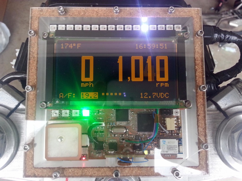
I had a Planar 160×80 EL graphic display that’s been in my parts bin for years that I’ve always wanted to use, and this was perfect. Unfortunately it doesn’t have a controller so I had to interface it to the CPU with an Epson S1D13700 graphic controller. The display indicates speed from a GPS module, air/fuel ratios from the wideband O2 sensor, engine temp, battery voltage, time from GPS, and RPM. I used a light sensor to sense ambient brightness levels and dim the display by changing TC/R in the graphics controller. The refresh of the display is high enough to allow a large dimming range without flickering. The EL display can be refreshed at up to 240Hz. The light sensor also controls the brightness of the bar graph and indicator LEDs. A BC127 bluetooth module allows datalogging via SPP, and I might eventually get around to displaying SMS messages from my phone on the display which was one of the design goals but isn’t done yet.
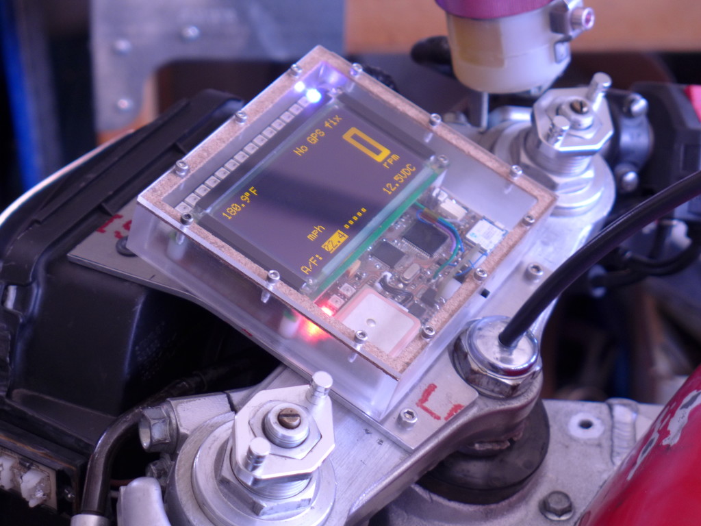
An IR optoisolator senses RPM pulses from the magnetic pickup and protects the system from ignition noise. Addressable LEDs function as indicator lights as well as forming the bar graph at the top of the display. The bar graph can display RPM, battery voltage, engine temp, or A/F ratios depending on the current mode which is selected by a button on the side of the housing. The bar graph is also a two stage shift light which overrides any display mode and goes to full brightness with two different colors to indicate high RPM for shifting. A highlight box on the graphics layer shows which mode is currently active and the graphic and text layers are XOR’ed. I also made a custom bitmapped font I thought went well with the display size and the amount of characters.
› Continue reading
PAR / Spectrum analyzer
I’ve been working on an off for a while on a project to measure photosynthetically active radiation (PAR) as well as analyze electromagnetic spectrum with the same sensor, at the same time. The spectrum in question is approximately 350-750nm. I mainly envisioned this tool for use with marine aquariums, and if things were going better I probably would have built a prototype.
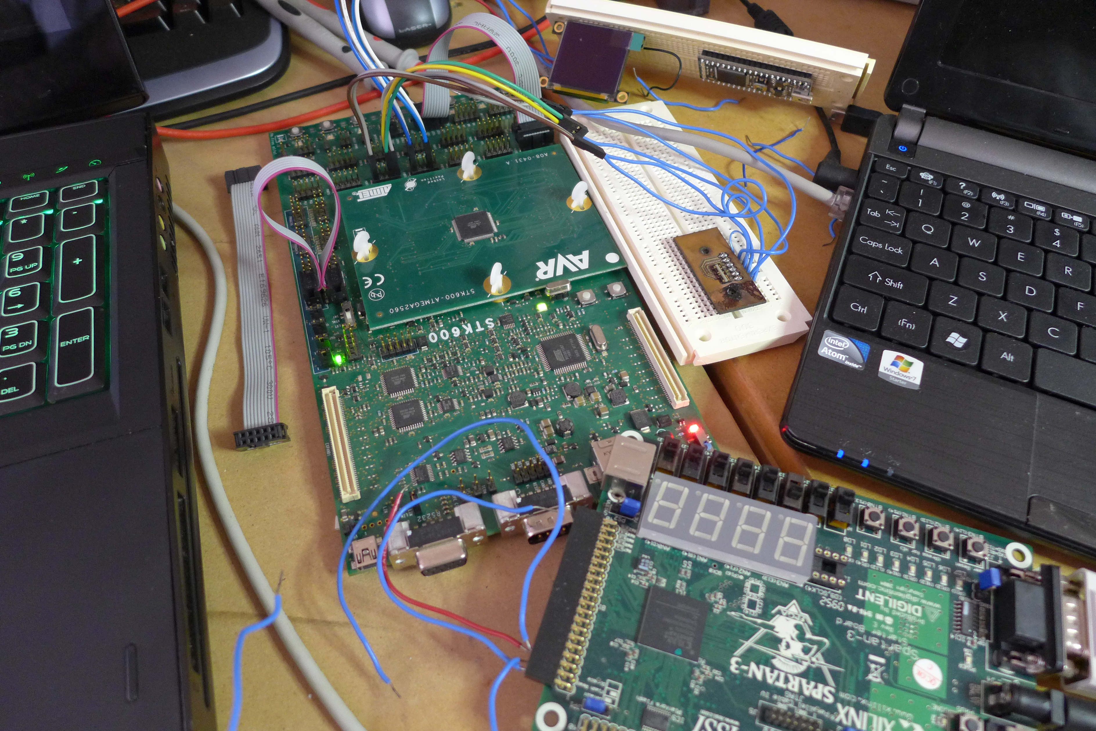
The sensor is a TAOS TSL3301CL. It is a 102-pixel photodiode array with a serial interface. The sensor contains analog stages for gain and offset as well as ADCs that sample the values and read the results to the serial port. It’s a nice device, but I haven’t been able to get what I want out of it. The response for me has been very non-linear. It’s also a very tiny leadless package so it’s not easy to work with.
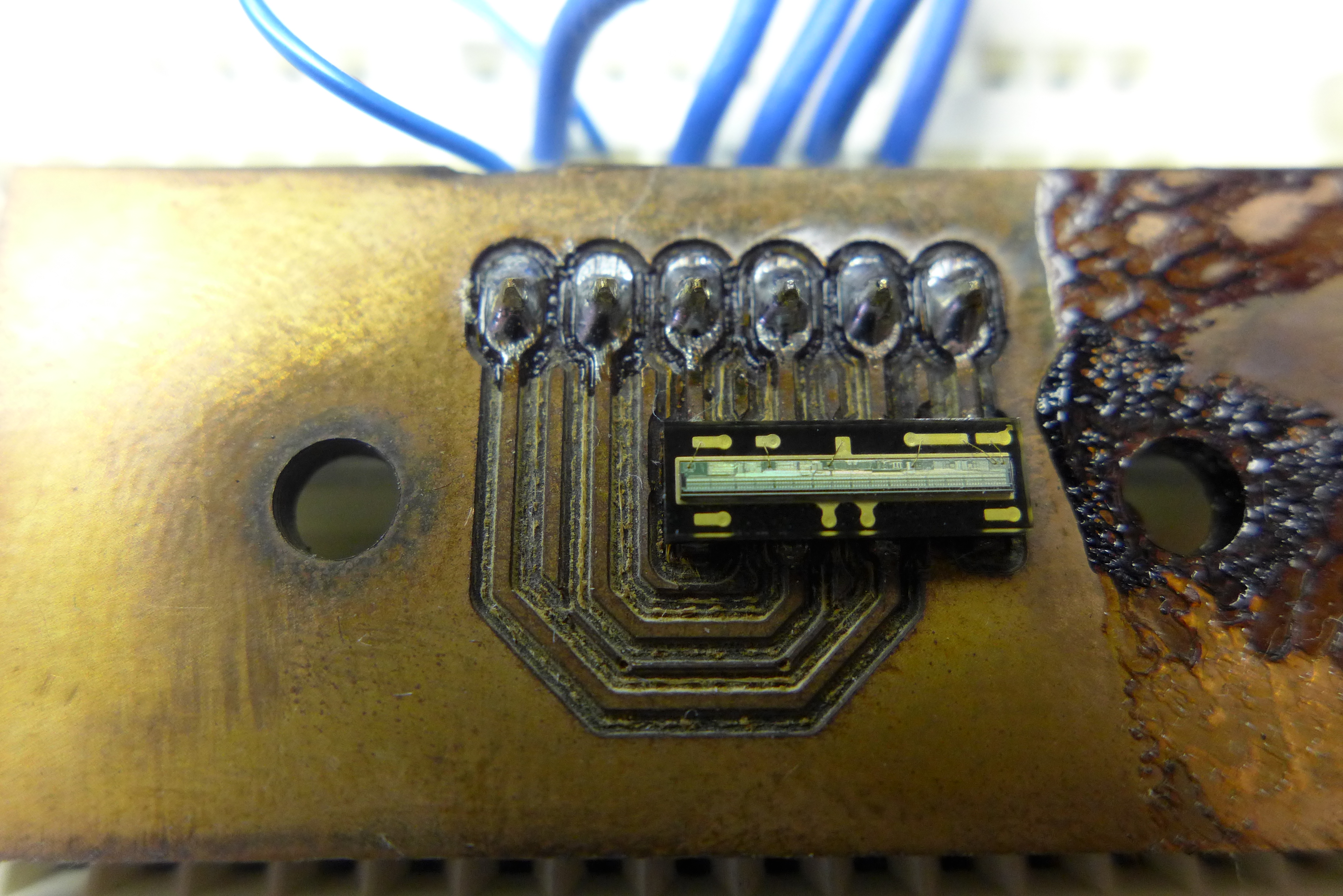
For reference, that is a 0.1″ header
My plan was to enclose the sensor in a housing with a series of lenses designed to introduce chromatic aberration or a prism to refract the captured ambient light, and then direct the spectral components of the light towards the sensor. The sensor’s response to wavelength is non-linear, but that can be corrected with a function in software for each pixel.
I had a uOLED 128×128 pixel display that I used to display the intensity of light for each pixel. This worked well, and I would have used an averaging function to estimate PAR from that data.
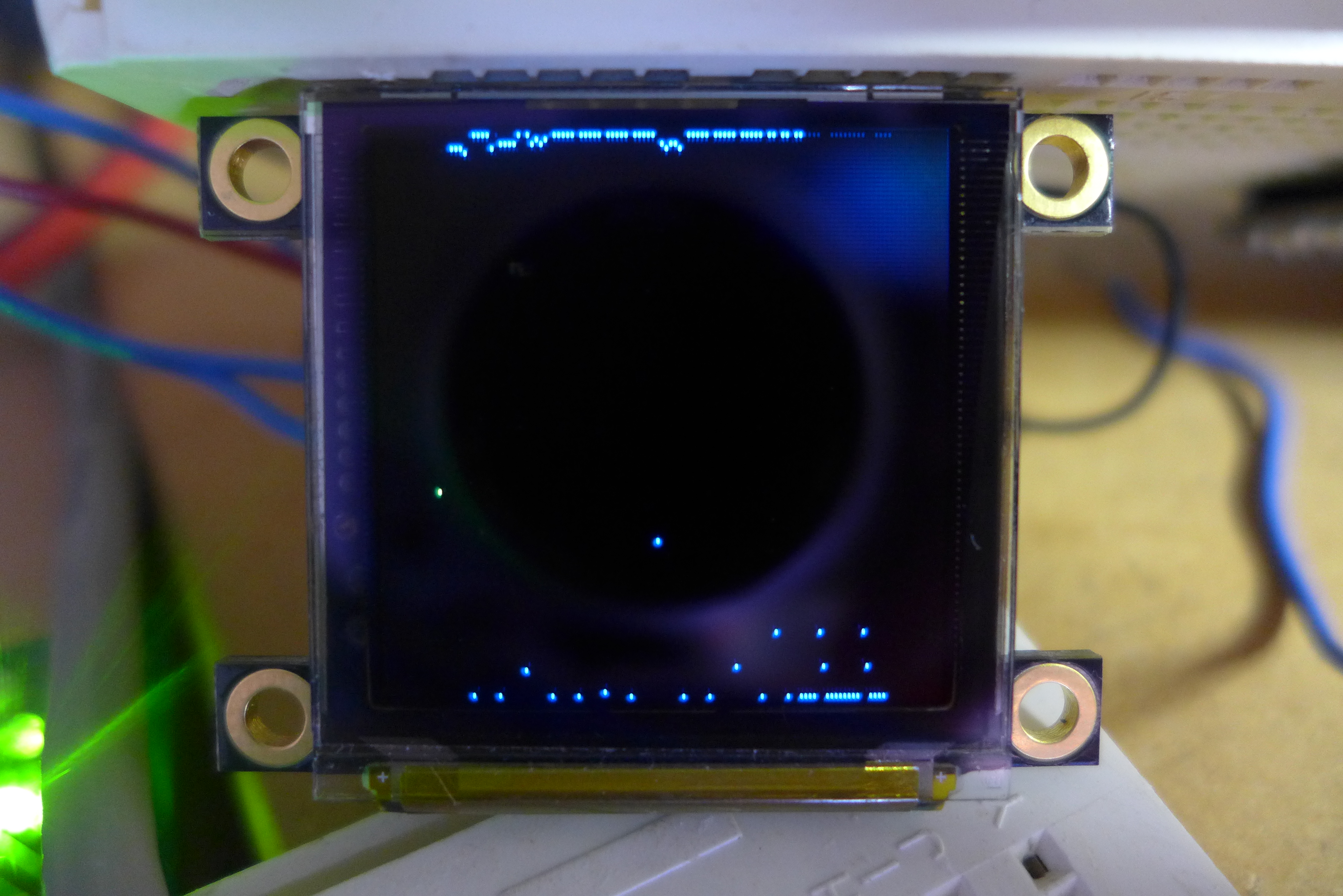
However, I haven’t been able to get the sensor to respond in what I consider a linear fashion. It is mostly on or off. Moving the light source back and forth from the sensor doesn’t result in any gradient that could be considered measurable. I’ve tried various gain and offset levels, as well as long and short integration times but with no success.
I originally tested it with an mbed, but I had trouble with the sensor’s synchronous clock. So I ported the code to the mega2560 on my STK600. About that time the display started to die and I don’t have another graphic display at the moment without messing around with an Epson S1D1335 and another graphics library… As such I’m stashing this project for now. If anyone has worked with these sensors before and knows what I’m doing wrong, I’d like to hear from you.
Pressure mapping with DIY foam load cells
I had an idea a while back to make a pressure sensing pad for testing saddle fit on horses. The intent was to create an array of pressure sensing cells, which could then be used to produce a pressure map that would represent any pinch points on a horse’s back. I found that you can buy this sort of thing, but it’s way too expensive for the average guy. I decided to try and make my own for cheap. I ended up making one from a handful of copper-clad PCBs and 1/4″ shipping foam.

The active area of the pad is approximately 2′ x 2′. I think the foam is polyurethane open-cell foam but I’m not sure. It’s the stuff you use to pack shipping crates. The load cells are made by sandwiching the foam in between 1″ circle cutouts of copper-clad FR4 PC board. I used single sided board and a hole saw with the pilot bit removed (use a drill press and a clamp). The capacitance varies as the foam compresses, and the amount of capacitance is directly related to the thickness and density of the foam, as well as the area of the copper conductors (plates). So you can create any size or thickness load cell you want really. A bigger plate results in more capacitance, as does placing the plates closer together. I estimated the capacitance I would have in my application with this calculator I found at Daycounter engineering services.
I created an array of 64 cells by making 8 rows and 8 columns, each with 8 copper-clad discs. Wherever the row/column discs align a load cell is created. An AVR typically has eight available ADC inputs along with another eight control outputs, so this way you can scan down through the rows and columns to measure each cell. A square wave is sequentially output on the columns, and after some analog proccessing the AVR’s ADC scans each row. The analog voltage present represents the amount of pressure (capacitance) at each site. › Continue reading
SMS remote control
I’ve been expirimenting with cheap GSM cell phones as remote control devices. I wanted to be able to control stuff at my house just by sending a text from my phone. I also wanted to use an AVR since the options are pretty limitless as to what you can control. I started off simple with relay outputs for stuff like the garage door, outside lights, etc. It could also be useful for the AVR to send texts based on events, but I haven’t messed with this yet.

I planned on just having the AVR recognize a particular text string, like “open garage” if I wanted to let someone in my house when I’m not there without giving them a key for example. It’s not overly secure, but you could add a number sequence as a prefix to the command that would be like a password. Then you could periodically change your password if you wanted. › Continue reading
Build a spot welder from a battery charger
I ran across a battery charger a while ago that was collecting dust. I looked inside and saw the transformer, heatsinks, high current bridge rectifier and SCR and knew I could do something with it. So I turned it into a spot welder.

I originally intended this project to weld thin sheetmetal tabs to stuff to act as solder tabs. The project has not been as easy as I originally thought though. (It also suffered some scope creep) It’s my first crack at 5V logic mixed with line AC voltage, and for rolling my own power supply. I used a step-down transformer, bridge regulator and a capacitor to feed an LDO regulator for the control circuit. With the low current draw of the controller, the voltage input to the regulator was relatively free from any ripple thanks to the capacitor.
I ended up frying a processor, LCD, and a couple other components due to a dumb move while troubleshooting the circuit, and overlooking a capacitor’s voltage rating. 120VAC will eat 5V stuff for lunch.

The control circuit basically modulates the SCR, which is hooked up to the output of the bridge rectifier after a step-down transformer. The controller allows for adjustment of duration of the weld and amount of the rectified AC phase that is delivered to the workpiece. The controller holds off the SCR until a pre-determined time of each half phase to control power delivery. An analog comparator detects the zero point of the phase for timing purposes, via a seperate bridge rectifier that has it’s ouput fed through a large resistor to the comparator. A zener clamps the current-limited voltage at 4.8V so as not to damage the micro’s input. A high-to-low transition on the comparator triggers the zero crossing timer. The threshhold voltage is adjustable by an on-board pot.
I also added an Allegro hall effect current sensor that I had lying around from my alternator current sense project. It’s overkill, but it measures the amount of peak current being delivered and displays it on the LCD.

The controller is an ATmega88PA running at 8Mhz. Firmware is written in C with AVRStudio and AVR-GCC. The micro reads the power and duration settings, displays that on the LCD, along with the max current for the last weld cycle and the temperature of the mega’s on-chip sensor. The controller also handles timing duties, zero crossing detection, and control of the SCR gate. The gate is fired by a P-channel MOSFET, with the FET’s gate driven by an NPN BJT on one of the micro’s pins. A footswitch is used as input to the micro to trigger a weld cycle. Both the footswitch input and the zero crossings are buffered by a simple three-sample debouncing routine to prevent erroneous triggers. The system also checks for the footswitch input on power up and after the weld cycle is complete, and waits if the footswitch is down with a message on the LCD to release the footswitch. This allows for safety as well as eliminating any unintended re-triggers at very short durations. Duration is adjustable from roughly one ac cycle to 60 cycles (1 sec). Power control allows from 5% to 95% of each half phase to be delivered to the workpiece.
The SCR’s cathode voltage is available at PORTC2 as a 10:1 voltage divider, and clamped with a zener to prevent damage to the micro. I didn’t need it, so it’s not used in the code.
I’ve also added a power resistor to the output to limit current. I used carbon-carbon as a power resistor (I work in a carbon plant) since it’s free and power resistors are expensive. You only need a few tenths of an ohm to limit the current to a level that won’t destroy the diodes and SCR. I’m overdriving mine at about 130A maximum. It seems to handle it fine for the short bursts. [Edit: 130A isn’t enough though. I may rewire so the diodes/SCR are on the input side and push the current higher by removing or modifying the resistor. Pressure of the electrodes on the joint is also important, still figuring that out.]
Here’s some drive waveforms: yellow is the output voltage (it’s at 50V/div so it looks small), purple is the output current measured by the hall sensor, blue is the FET’s gate that turns on the SCR, and green is the bridge voltage.


This project has got me thinking about modifying my old “buzzbox” AC welder. I’ve got some big capacitors and IGBTs from a couple old motor drives that could give me a really nice TIG welding power supply. I think I’ve read you can weld high frequency (1-2kHz?) square-wave without needing any HF section. If I remember right square-wave with a positive DC offset is sort of the ultimate TIG welder. Anybody with comments or information about that feel free to drop me a line.
Continue reading for the schematic, PCB layout, and code.
References: Miller Resistance Spot Welding
Turn signals for a trailer
I’ve been working intermittently on a project to come up with a way to add turn signals to the side of a trailer without needing any extra wiring from the truck. The way people normally do this is by tapping the side markers into the turn signal wires. However, that makes the side markers turn on and off with the brakes which makes for a confusing signal. There is no shortage of patents for adding this type of capability, but they usually require a unique transmitter aboard the truck that communicates with another unique receiver on the trailer. Since the 6 pin standard is ubiquitous, that type of system will likely not be available or popular for some time. I didn’t want to add any special hardware to the truck either. So I’ve been working on a solution that taps into the trailer’s main electrical harness and creates an extra side turn signal for each side of the trailer and also functions as a clearance light.

You can use any standard clearance light and it will function as a clearance light when the lights are on, and also flash that light when the appropriate turn signal is on. The brakes will not cause the side markers to flash. You can add new lights, or simply intercept the wiring to existing clearance lights. The only modification is to the trailer, and it will work the same for any truck. The only requirement is that the trailer has electric brakes and the truck has a brake controller.
My code is running on an ATtiny24, on a board I prototyped just for this. I built an in-line harness for testing that passes the signals from the 6 pin connector to the trailer, but taps into those signals for the logic. My device has two standard LED clearance lamps attached as left and right turn signals for testing. This system is an add-on to the existing trailer wiring, so in the event of a failure nothing is compromised.

It has been tough getting this working, as there’s not exactly a manual for how the truck and the brake controller handle the signals. It’s taken a few months, as evidenced by the tarnished PCB. If I remember right I made it this summer.
Digital RPM indicator

I made a circuit for RPM measurement based on an Atmel ATtiny24 to drive a Hitachi 44780 parallel interface character LCD. It uses an external interrupt request and INT0 to calculate the elapsed time between high/low transitions on the INT0 pin. The elapsed time is then converted to RPM and sent to the LCD. The code will work from RPM values up to 999, and a variable timeout is used for a low cutoff to display 0RPM. The RPM range could be extended to 9,999 or higher by modifying the decimal to BCD routine at the end of the program.

Here is the source code, it compiles with AVR Studio and AVR-GCC. › Continue reading
How much electric current does a truck really use?
So, a while back my truck was getting slow to start. I checked the battery voltage with the truck running, and it was only 11 volts or something. I started the troubleshooting process by replacing the alternator with one from the local parts store, but it didn’t fix the problem. I changed both batteries. Still didn’t fix the problem. So I did some diagnostics with an ammeter and a voltmeter and figured out that my brand-new alternator was bad. I took it back to the parts store, where they gave me another one. I had them test it, and it failed on their bench tester. So did the next one. They finally gave me my money back and I bought one from Ford. It worked just fine.
While I was looking for alternators, I found some high output models. This sounds cool, but do you really need it? I pull a trailer pretty regularly, and I imagined that the trailer lights and brakes would be a pretty good additional load on the electrical system. I had also read that people buying these “high output” alternators had been disappointed with their actual output, so I thought it might be good to find out.
I wasn’t sure how dirty the output of the alternator would be, or how quickly the output might fluctuate which ruled out the use of an inductive current clamp. So I looked around and found a hall-effect current sensor from Allegro Microsystems. The manufacturer’s part number is ACS758KCB-150B-PFF-T. This sensor has a maximum current rating of 150 Amps, and outputs a linear 0-5V signal proportional to the current that passes through the device. It’s fast enough to record transients and will faithfully reproduce both AC and DC currents. The output of the sensor was fed to an Atmel ATMega8, which did ADC duties and sent the data out it’s UART to a MAX232 level converter. I just picked up the data stream with hyperterminal on my laptop. Excel let me manipulate the raw data and make some pretty graphs. I made the circuit with my CNC machine. Here’s what it looks like.

The output of the alternator was alot cleaner than I had expected. I thought there would be more of a rectified three phase look due to the phases generated inside the alternator. This picture of the scope shows the trace of the output of the sensor at idle.

Here is a graph of the data from an engine start up. The Y-axis values are actual current draw in Amps. Time is shown on the X-axis, but the numbers represent the conversion events of the ADC, which happen at approximately 15Hz. This equates to about 40 seconds. The noise is real as far as I can tell. I didn’t use a ground plane, but the trace from the sensor output to the Mega’s ADC input is only about a quarter of an inch. I added a large filter capacitor to the sensor’s output and the waveform didn’t change at all. *edit: I messed that up though, I wasn’t paying attention to where I put it.*

Then I took the truck for about a ten minute drive. I had the lights on, but not the radio or anything extra.

It’s interesting to note how much power the transmission consumes when it’s in gear. The first plot is idling in park, the second plot again shows the truck idling in park at the end of the plot. It’s a clear 20 Amp drop from when the truck was in drive.
I hooked up my horse trailer, but even with all the lights on and everything it only shifted the curve up 10 Amps. The trailer brakes (which I thought would be a significant load) didn’t even show up. I’m still curious about this, as the trailer brake control wiring is usually about 10-12 guage, which is almost the same gauge wire the alternator output has to connect it to the battery. Why bother to wire trailer brake wiring with wire that has an ampacity of 100 Amps or so if it only uses a few amps? There must be more to the story.
Here is the schematic. Sorry it’s not all labelled but I didn’t expect to be posting it at the time. Click on the image to view full size. Capacitors C1 and C2 are for the crystal, 22pF. Capacitors C3-C10 are decoupling capacitors or buffers for the power supply. C11-C14 are typically 1uF. Check the component datasheets for your application.
** I keep getting requests for values, so here is some more detail. The oscillator value is not important, I probably used 8MHz. This circuit doesn’t need high speed. C3 and C4 are decoupling capacitors, usually 0.1uF. C5 and C6 are not necessary, I just added them for flexibility since it was a prototype board. All you need there is C15 which is a bulk capacitor for the voltage regulator. I can’t remember what C7 is, it’s in the AVR datasheet. C9 and C10 aren’t necessary, I was trying to implement a low pass filter but it’s incorrect. All C9 and C10 will do is cause the sensor to drive the output harder. I needed an RC filter but only got the C. That should cover it.

And here’s the layout.

I neglected to add a header for ISP. I was in a hurry to get it done and forgot. The target supply voltage in this application is 11-14V, but supply voltage could be extended to +45V with the appropriate version of the 7805.
Here’s the source code for the Mega8. Compiles with AVR Studio and AVR GCC. It’s a timer-driven interrupt, that starts an ADC conversion of the sensor output and then sends the result to the UART. It uses standard 9600 8N1. The result is left-adjusted so it’s only 8 bit. If you don’t need both positive and negative current measurements, then it would be best to remove the offset of the sensor and use the internal 2.5V ADC reference for better accuracy. The decimal to BCD routine at the end is something I figured out so I can just do a file capture in hyperterminal and import it directly into Excel. › Continue reading
Other Stuff
- 0.008″ PCB trace isolation on my CNC
- 1_Wire_Driver
- 12 Volts on the trailer without a truck
- 330 Watt power supply for Alienware M17x
- 330W power supply for M17x update
- 6970m power issues
- 6970m vBIOS ISP / Pm25LD010
- 6CY7 dual triode valve amplifier
- Acrylic polishing and scratch removal
- Air quality sensor (TVOC and eqCO2)
- Alienware AlienFX repair
- Alienware M17x BIOS / EC corrupted flash fix
- Atmel’s new micro with integrated boost converter
- Automotive rear fill “surround sound” with Boss DD-3
- Breathe life into your Xoom
- BT5 USB flash drive persistent install
- Build a 9-digit Pulse Counter for under $20
- Build a spot welder from a battery charger
- Canon A70 CCD replacement
- Canon DSLR shutter release from any switch contact
- Cascade process heater
- CNC version 2.0
- Continuous vs. batch water changes
- Diesel, sulfur, NOx, and EGR
- Digital RPM indicator
- DIY Router table
- Ducati 749/999 Tail Light
- Electronic choke
- ELM327 emulator
- Fast idle mod
- Fix your Keurig
- Fix your Keurig – again
- Flash a monitor’s EDID with an mbed and RealTerm
- Flatbed scanner panoramic camera
- Forza 3 multiscreen setup
- GSXR Instruments C Source
- Horizont: a true panoramic camera
- How much electric current does a truck really use?
- Instruments for the GSXR
- LED backlit desk sign
- Light pipe tail light for the GSXR
- M17x 6990m / 6970m overheating
- M17x inverter brightness fix
- MAX4173 Current sense amplifier
- mbed 1-wire EPROM driver (DS2502)
- MEMS Accelerometers
- Modifying a digital camera for infrared (IR) photography
- Moisture Meter for Plants
- My homebuilt CNC machine
- Netgear WGR614v7
- Netgear wireless router repair
- PAR / Spectrum analyzer
- PCB layouts and schematics for my CNC
- PIC32 Ethernet Starter Kit and MPLAB X
- Piezo pump
- Pressure mapping with DIY foam load cells
- SMS remote control
- Sony VAIO FW series laptop battery hack
- SPI programmer for SST25VF016B
- Spring tester / weight scale
- Spring tester C source
- Strain-Guage based Pressure Sensor
- Textile needle loom
- Trailer turn signal update
- Training halter fixes pulling back, lunging problems
- Turn signals for a trailer
- Upgrade M17x R1 to R2 motherboard
- Xbox 360 red lights issue
Recent Posts
Archives
- May 2019 (2)
- April 2017 (3)
- October 2015 (1)
- May 2015 (1)
- March 2014 (2)
- December 2013 (1)
- July 2013 (1)
- November 2012 (1)
- October 2012 (4)
- September 2012 (1)
- August 2012 (3)
- June 2012 (1)
- March 2012 (1)
- February 2012 (1)
- January 2012 (1)
- October 2011 (3)
- July 2011 (1)
- June 2011 (3)
- May 2011 (2)
- April 2011 (1)
- December 2010 (1)
- August 2010 (1)
- July 2010 (3)
- April 2010 (2)
- March 2010 (2)
- January 2010 (2)
- December 2009 (2)
- October 2009 (2)
- September 2009 (1)
- August 2009 (15)