Archive for December, 2009
Turn signals for a trailer
I’ve been working intermittently on a project to come up with a way to add turn signals to the side of a trailer without needing any extra wiring from the truck. The way people normally do this is by tapping the side markers into the turn signal wires. However, that makes the side markers turn on and off with the brakes which makes for a confusing signal. There is no shortage of patents for adding this type of capability, but they usually require a unique transmitter aboard the truck that communicates with another unique receiver on the trailer. Since the 6 pin standard is ubiquitous, that type of system will likely not be available or popular for some time. I didn’t want to add any special hardware to the truck either. So I’ve been working on a solution that taps into the trailer’s main electrical harness and creates an extra side turn signal for each side of the trailer and also functions as a clearance light.

You can use any standard clearance light and it will function as a clearance light when the lights are on, and also flash that light when the appropriate turn signal is on. The brakes will not cause the side markers to flash. You can add new lights, or simply intercept the wiring to existing clearance lights. The only modification is to the trailer, and it will work the same for any truck. The only requirement is that the trailer has electric brakes and the truck has a brake controller.
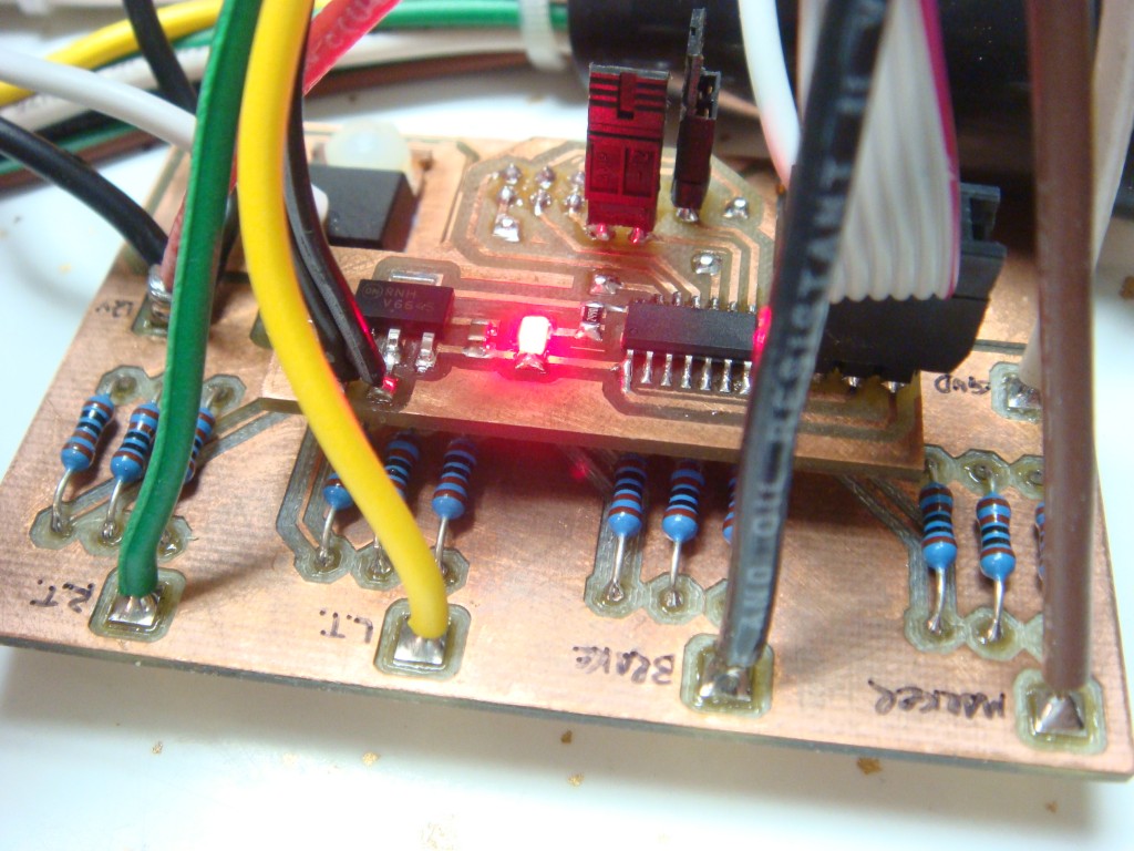
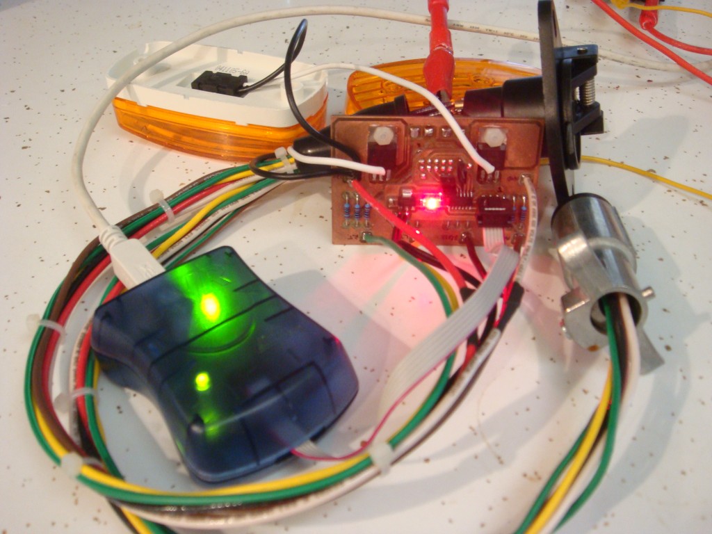
My code is running on an ATtiny24, on a board I prototyped just for this. I built an in-line harness for testing that passes the signals from the 6 pin connector to the trailer, but taps into those signals for the logic. My device has two standard LED clearance lamps attached as left and right turn signals for testing. This system is an add-on to the existing trailer wiring, so in the event of a failure nothing is compromised.

It has been tough getting this working, as there’s not exactly a manual for how the truck and the brake controller handle the signals. It’s taken a few months, as evidenced by the tarnished PCB. If I remember right I made it this summer.
Xbox 360 red lights issue
A few days ago (just in time for Christmas break) my Xbox 360 started crashing and then gave me 3 red lights, indicating a hardware failure. This is really lame, since I just got hooked on Forza 3, and now I won’t be able to play it over my break from school and work. Thanks Xbox.
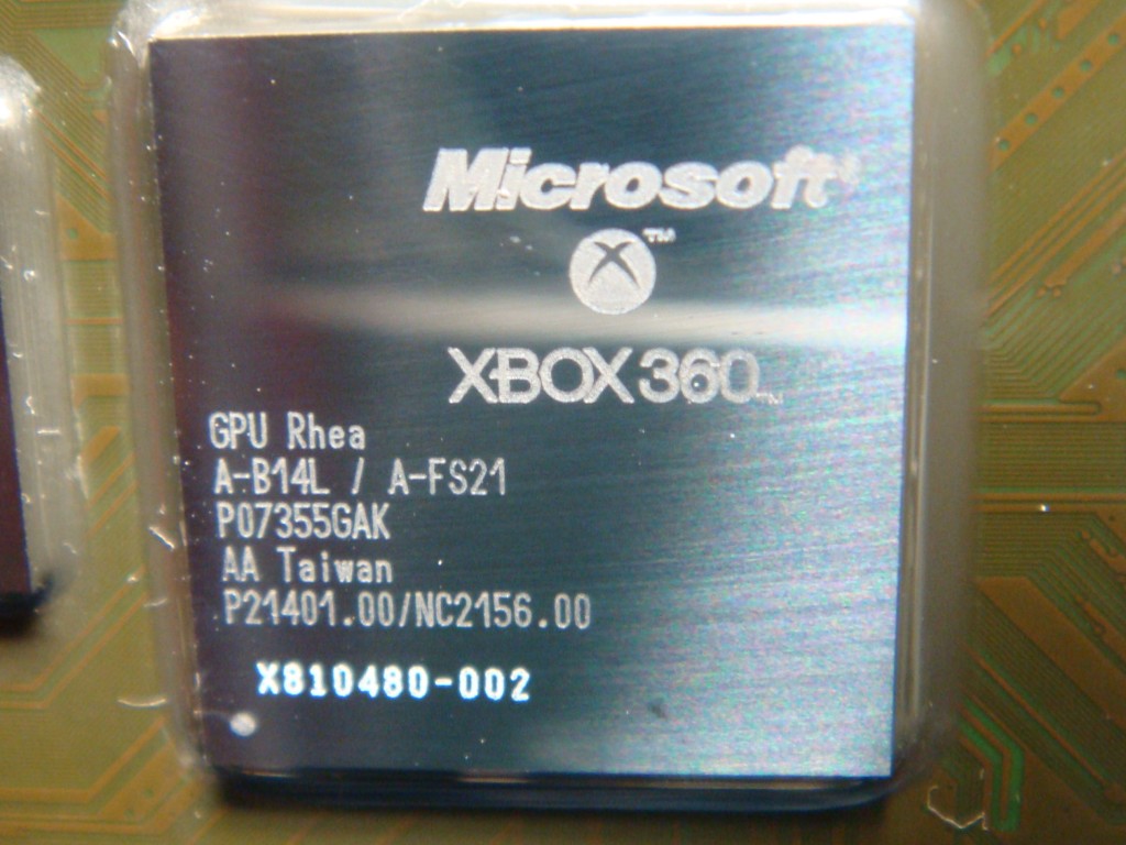
I looked up the reason for the red lights, since I can usually find a way to fix stuff. The consensus is that the GPU interface suffered a manufacturing problem due to lead-free solder where the BGA solder balls develop cracks over time. Sounds reasonable. The “fixes” seem to either be reballing the GPU (expensive) or a supposed reflow process that just overheats the GPU.

I tried this one first, since there wasn’t much to lose anyway. The theory is that you can reflow the BGA solder balls and restore electrical contact between the GPU and the PCB by just overheating the GPU. I am pretty skeptical that this is possible, as I don’t think a chip is capable of heating itself to the 320+ °F necessary for solder to melt and flow without damaging itself. Transistors tend to flow a lot of current when they get hot, which would likely damage the processor. At any rate, I tried it. It worked for a day. I wish I would have instrumented the GPU so I knew the peak temperature, but I forgot.
So then I tried to actually reflow the GPU. I tried 5% rosin no-clean flux, and saturated the GPU/PCB interface. I preheated the board to 300°F by setting it on a heated stir plate. I had a fine-gauge K-type thermocouple tucked just under the die so that I could measure the temperature. I heated the die with a hot-air station to 420°F over 2 minutes, and then increased to 450-475°F and held for about 30 seconds.
After the board cooled, I put it back together and plugged it in. Still got three red lights. I took it back apart again and did the same thing to the CPU, but still had the same problem. Then I tried again with 30% rosin flux and slightly higher temperatures. Same three red lights. I suppose the board is junk now, but I still am curious why it worked again after heating the board up a little bit from overheating the GPU. It tells me that most of the fixes out there for “reflowing” aren’t actually doing so, instead they are just creating enough stress on the PCB to fix whatever joint is intermittent. For example, one person supposedly reflowed his entire board in his kitchen oven. I’m not an expert in PCB manufacturing, but if the whole board is at reflow temperature, won’t the RAM chips (and most components) on the bottom side just fall off? There can’t be enough surface tension from the solder balls to actually hold the chip in place upside down.
I did some more digging and found out that you can in fact get error codes without video out. There is a lot of good information at xbox-experts.com. I found out that I have a “bridged solder joint/short GPU/HANA”. I wonder if it’s because of my novice “reflow” skills. I can solder with the best of them, but this is totally different. Wish I had started there first.
That’s one of the funny things about modern manufacturing- it makes something hard look really easy.
References:
http://www.altera.com/literature/an/an353.pdf
http://www.altera.com/literature/wp/wp_chmfgrelldfr.pdf
http://www.altera.com/literature/an/an081.pdf
Other Stuff
Recent Posts
- 6CY7 dual triode valve amplifier
- Air quality sensor (TVOC and eqCO2)
- Automotive rear fill “surround sound” with Boss DD-3
- Spring tester / weight scale
- Ducati 749/999 Tail Light
- Instruments for the GSXR
- Light pipe tail light for the GSXR
- M17x 6990m / 6970m overheating
- PAR / Spectrum analyzer
- Acrylic polishing and scratch removal
Archives
- May 2019 (2)
- April 2017 (3)
- October 2015 (1)
- May 2015 (1)
- March 2014 (2)
- December 2013 (1)
- July 2013 (1)
- November 2012 (1)
- October 2012 (4)
- September 2012 (1)
- August 2012 (3)
- June 2012 (1)
- March 2012 (1)
- February 2012 (1)
- January 2012 (1)
- October 2011 (3)
- July 2011 (1)
- June 2011 (3)
- May 2011 (2)
- April 2011 (1)
- December 2010 (1)
- August 2010 (1)
- July 2010 (3)
- April 2010 (2)
- March 2010 (2)
- January 2010 (2)
- December 2009 (2)
- October 2009 (2)
- September 2009 (1)
- August 2009 (15)