How much electric current does a truck really use?
So, a while back my truck was getting slow to start. I checked the battery voltage with the truck running, and it was only 11 volts or something. I started the troubleshooting process by replacing the alternator with one from the local parts store, but it didn’t fix the problem. I changed both batteries. Still didn’t fix the problem. So I did some diagnostics with an ammeter and a voltmeter and figured out that my brand-new alternator was bad. I took it back to the parts store, where they gave me another one. I had them test it, and it failed on their bench tester. So did the next one. They finally gave me my money back and I bought one from Ford. It worked just fine.
While I was looking for alternators, I found some high output models. This sounds cool, but do you really need it? I pull a trailer pretty regularly, and I imagined that the trailer lights and brakes would be a pretty good additional load on the electrical system. I had also read that people buying these “high output” alternators had been disappointed with their actual output, so I thought it might be good to find out.
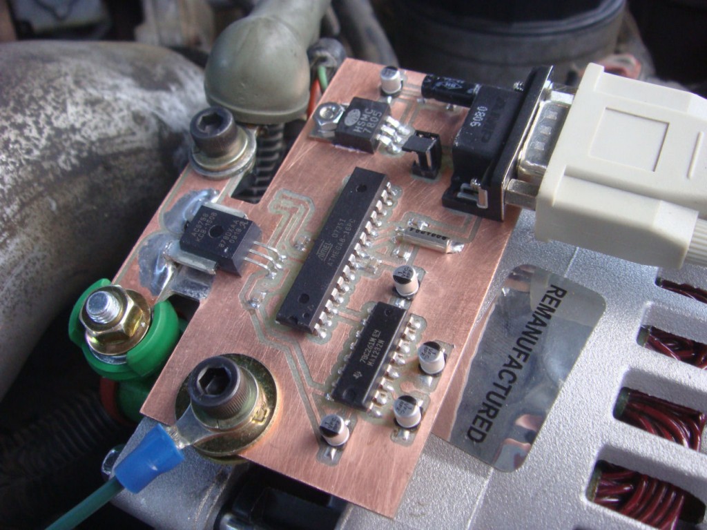
I wasn’t sure how dirty the output of the alternator would be, or how quickly the output might fluctuate which ruled out the use of an inductive current clamp. So I looked around and found a hall-effect current sensor from Allegro Microsystems. The manufacturer’s part number is ACS758KCB-150B-PFF-T. This sensor has a maximum current rating of 150 Amps, and outputs a linear 0-5V signal proportional to the current that passes through the device. It’s fast enough to record transients and will faithfully reproduce both AC and DC currents. The output of the sensor was fed to an Atmel ATMega8, which did ADC duties and sent the data out it’s UART to a MAX232 level converter. I just picked up the data stream with hyperterminal on my laptop. Excel let me manipulate the raw data and make some pretty graphs. I made the circuit with my CNC machine. Here’s what it looks like.
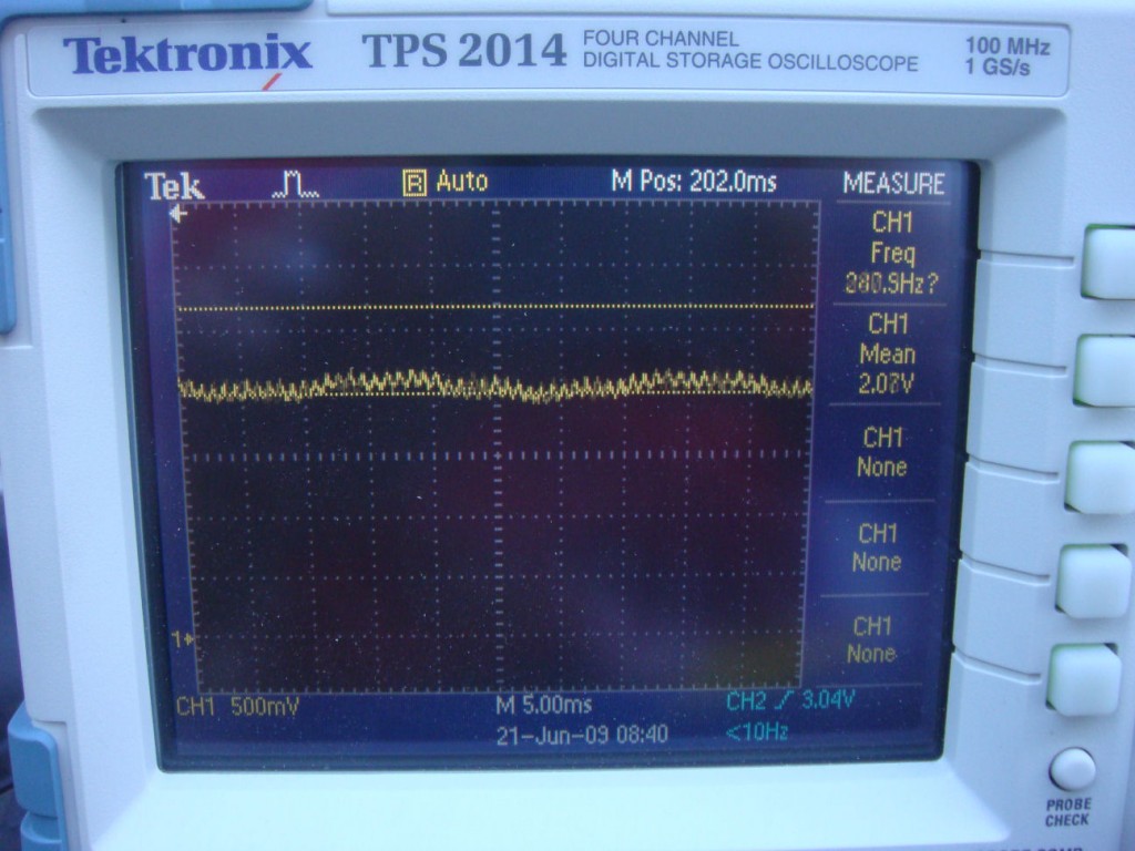
The output of the alternator was alot cleaner than I had expected. I thought there would be more of a rectified three phase look due to the phases generated inside the alternator. This picture of the scope shows the trace of the output of the sensor at idle.
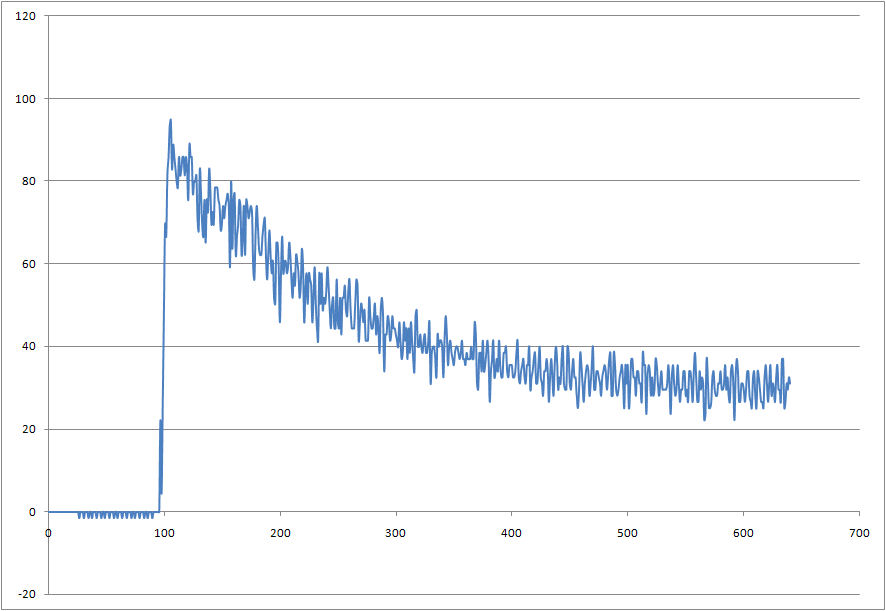
Here is a graph of the data from an engine start up. The Y-axis values are actual current draw in Amps. Time is shown on the X-axis, but the numbers represent the conversion events of the ADC, which happen at approximately 15Hz. This equates to about 40 seconds. The noise is real as far as I can tell. I didn’t use a ground plane, but the trace from the sensor output to the Mega’s ADC input is only about a quarter of an inch. I added a large filter capacitor to the sensor’s output and the waveform didn’t change at all. *edit: I messed that up though, I wasn’t paying attention to where I put it.*
Then I took the truck for about a ten minute drive. I had the lights on, but not the radio or anything extra.
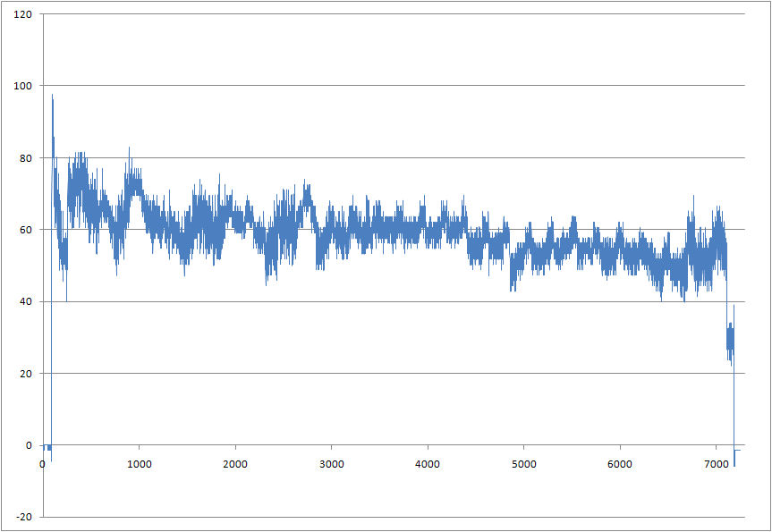
It’s interesting to note how much power the transmission consumes when it’s in gear. The first plot is idling in park, the second plot again shows the truck idling in park at the end of the plot. It’s a clear 20 Amp drop from when the truck was in drive.
I hooked up my horse trailer, but even with all the lights on and everything it only shifted the curve up 10 Amps. The trailer brakes (which I thought would be a significant load) didn’t even show up. I’m still curious about this, as the trailer brake control wiring is usually about 10-12 guage, which is almost the same gauge wire the alternator output has to connect it to the battery. Why bother to wire trailer brake wiring with wire that has an ampacity of 100 Amps or so if it only uses a few amps? There must be more to the story.
Here is the schematic. Sorry it’s not all labelled but I didn’t expect to be posting it at the time. Click on the image to view full size. Capacitors C1 and C2 are for the crystal, 22pF. Capacitors C3-C10 are decoupling capacitors or buffers for the power supply. C11-C14 are typically 1uF. Check the component datasheets for your application.
** I keep getting requests for values, so here is some more detail. The oscillator value is not important, I probably used 8MHz. This circuit doesn’t need high speed. C3 and C4 are decoupling capacitors, usually 0.1uF. C5 and C6 are not necessary, I just added them for flexibility since it was a prototype board. All you need there is C15 which is a bulk capacitor for the voltage regulator. I can’t remember what C7 is, it’s in the AVR datasheet. C9 and C10 aren’t necessary, I was trying to implement a low pass filter but it’s incorrect. All C9 and C10 will do is cause the sensor to drive the output harder. I needed an RC filter but only got the C. That should cover it.
And here’s the layout.
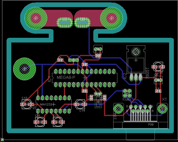
I neglected to add a header for ISP. I was in a hurry to get it done and forgot. The target supply voltage in this application is 11-14V, but supply voltage could be extended to +45V with the appropriate version of the 7805.
Here’s the source code for the Mega8. Compiles with AVR Studio and AVR GCC. It’s a timer-driven interrupt, that starts an ADC conversion of the sensor output and then sends the result to the UART. It uses standard 9600 8N1. The result is left-adjusted so it’s only 8 bit. If you don’t need both positive and negative current measurements, then it would be best to remove the offset of the sensor and use the internal 2.5V ADC reference for better accuracy. The decimal to BCD routine at the end is something I figured out so I can just do a file capture in hyperterminal and import it directly into Excel.
——————————————————————————————————————————
#include <avr/io.h>
#include <avr/interrupt.h>

#define F_CPU 8000000

#define USART_BAUDRATE 9600
#define BAUD_PRESCALE (((F_CPU / (USART_BAUDRATE * 16UL))) - 1)

void main(void)
{

UCSRB |= (1 << RXEN) | (1 << TXEN);  // Turn on the UART
UCSRC |= (1 << URSEL) | (1 << UCSZ0) | (1 << UCSZ1);  // Use standard 8N1
UBRRL = BAUD_PRESCALE; 	       // Load lower 8-bits of the baud rate value
                               // into the low byte of the UBRR register
UBRRH = (BAUD_PRESCALE >> 8);  // Load upper 8-bits of the baud rate value
                               // into the high byte of the UBRR register

TIMSK |= (1 << TOIE1);	       // Enable Timer1 overflow interrupt
TCCR1B |= (1 << CS11);	       // Turn on Timer1, CLK/8 prescale

ADMUX |= (1 << REFS0);	       // Select VCC reference
ADMUX |= (1 << ADLAR); 	       // Left adjust ADC result
ADCSRA |= (1 << ADEN) | (1 << ADIE);    // Turn on ADC and enable
                                        // conversion complete interrupt
ADCSRA |= (1 << ADPS1) | (1 << ADPS2);	// ADC prescale of CLK/64

sei();

while(1); {}

}

ISR(TIMER1_OVF_vect)
{

ADCSRA |= (1 << ADSC);	       // Start ADC conversion

}

ISR(ADC_vect)
{
unsigned long VOLTAGE = ((((ADCH/10)+((ADCH/100)*6))*16)+(ADCH%10));

unsigned int ONES = 0x00;
unsigned int TENS = 0x00;
unsigned int HUND = 0x00;

if((VOLTAGE & 0x0800) == 0x0800) HUND |= 0x08; else HUND &= ~0x08;
if((VOLTAGE & 0x0400) == 0x0400) HUND |= 0x04; else HUND &= ~0x04;
if((VOLTAGE & 0x0200) == 0x0200) HUND |= 0x02; else HUND &= ~0x02;
if((VOLTAGE & 0x0100) == 0x0100) HUND |= 0x01; else HUND &= ~0x01;

if((VOLTAGE & 0x0080) == 0x0080) TENS |= 0x08; else TENS &= ~0x08;
if((VOLTAGE & 0x0040) == 0x0040) TENS |= 0x04; else TENS &= ~0x04;
if((VOLTAGE & 0x0020) == 0x0020) TENS |= 0x02; else TENS &= ~0x02;
if((VOLTAGE & 0x0010) == 0x0010) TENS |= 0x01; else TENS &= ~0x01;

if((VOLTAGE & 0x0008) == 0x0008) ONES |= 0x08; else ONES &= ~0x08;
if((VOLTAGE & 0x0004) == 0x0004) ONES |= 0x04; else ONES &= ~0x04;
if((VOLTAGE & 0x0002) == 0x0002) ONES |= 0x02; else ONES &= ~0x02;
if((VOLTAGE & 0x0001) == 0x0001) ONES |= 0x01; else ONES &= ~0x01;

ONES |= 0x30;
TENS |= 0x30;
HUND |= 0x30;

UDR = HUND;				// Send the ADC results to the UART
while ((UCSRA & (1 << UDRE)) == 0) {}; 	// Wait for UDR to clear
UDR = TENS;
while ((UCSRA & (1 << UDRE)) == 0) {};
UDR = ONES;
while ((UCSRA & (1 << UDRE)) == 0) {};
UDR = 0x0D;				// Send new line
while ((UCSRA & (1 << UDRE)) == 0) {};
UDR = 0x0A;

}
40 Comments to How much electric current does a truck really use?
Leave a Reply
Other Stuff
Recent Posts
- 6CY7 dual triode valve amplifier
- Air quality sensor (TVOC and eqCO2)
- Automotive rear fill “surround sound” with Boss DD-3
- Spring tester / weight scale
- Ducati 749/999 Tail Light
- Instruments for the GSXR
- Light pipe tail light for the GSXR
- M17x 6990m / 6970m overheating
- PAR / Spectrum analyzer
- Acrylic polishing and scratch removal
Archives
- May 2019 (2)
- April 2017 (3)
- October 2015 (1)
- May 2015 (1)
- March 2014 (2)
- December 2013 (1)
- July 2013 (1)
- November 2012 (1)
- October 2012 (4)
- September 2012 (1)
- August 2012 (3)
- June 2012 (1)
- March 2012 (1)
- February 2012 (1)
- January 2012 (1)
- October 2011 (3)
- July 2011 (1)
- June 2011 (3)
- May 2011 (2)
- April 2011 (1)
- December 2010 (1)
- August 2010 (1)
- July 2010 (3)
- April 2010 (2)
- March 2010 (2)
- January 2010 (2)
- December 2009 (2)
- October 2009 (2)
- September 2009 (1)
- August 2009 (15)

Nice litte project this one!
I’m inspired to do a similar project, just for fun.
I read you’re using Hyperterminal and Excel.
You could pretty easy get rid of Hyperterminal and just use Exel, as it has VBA in.
Google ‘Visual Basic’ and ‘serial’ would give you a lot of examples to knick from.
Thanks, I’ll check that out. I didn’t know Excel could do that. One of these days I need to start learning VB so I can get more use out of Excel.
Great project(s)! I really like it.
[…] it can be to pin-point the source of your woes. Here’s a hackery solution that uses a diy PCB to monitor the current being drawn off of the alternator.The sensing is provided by an Allegro ACS758 integrated circuit. This chip […]
Very nice project.
I hope you’ll explain your findings on the brake box. Since I know typically a tandem trailer box will need a beefy 40amp fuse, it’s definitely a head scratcher. Unless the brakes are pulling juice directly from your break away box, and you’re simply trickle charging that battery.
BTW, gratz on being picked up by Hack a day.
Great bit of work beats a crappy analog meter. I also like the fact you can log the data to a file on your laptop and investigate problems on the move ie loose connections etc. Good Job.
-Jim
that’s because the current is needed to hold the internal valve open (like keeping the water heater valve open) for driving fluid to pass, to push the propeller for the driving
And the reason you run wires that’s able to handle hundreds of amps for only few amps, is resistance.
With this low resistance, no power is consumed as heat thru the wire, and all consumed on the load, like the lights.
Maybe the PCB-Copper area in the high current path plays into your calculations: http://circuitcalculator.com/wordpress/2006/01/31/pcb-trace-width-calculator/
Nice project. That is a cool hall-effect device! I like the quick and dirty data collection method, nice and simple.
Where were you 3 months ago when I was struggling with my electrical system in my little car? I put a sub in, and then went through three reman alts, and upgraded wiring before i decided to get a deep cycle battery from deka and a 180 amp alt from a custom builder. The whole time I was wishing I had this exact thing, but didn’t even think about building it myself. I really have to drop in here more often!
Nice work – I was looking for a logger for my wind turbine, this will be perfect! Thanks
You can also take the output to a simple led driver for a bar graph display. I forget the chip I used to make a voltage display for one of my older cars, but it was really simple. Great job!! I know what I’ll be building next.
I’ve worked towards doing pretty much this exact thing. Allegro offers evaluation boards (ASEK713ELC-20A-T) for $20 based on the ACS713 (and similar) parts. These generally support uni-polar (positive current only) and bi-polar (Pos and Neg current) current sensors in the 5-30 Amp range. The actual sensor can be swapped out as your needs change.
My project is related to measuring the current one of my appliances draws when powered from 120VAC or 12VDC, and the one eval board works in both situations. The sensor would drive a controller with a 10- or 12-bit ADC (PIC18Fxxxx) which would do the same thing as the Atmel controller here. A connected PC would log the results over time for processing later.
It helps that I have a couple of Allegro and Microchip demo boards that can simply be wired together so I don’t actually have to build much hardware (think building blocks).
Hey. I couldn’t get through to this page the other day. Anyone else had the problem?
I think this is going on my list of things to build! I hope you post schematics for your other projects as I was hoping to design and diy a few of them myself!
Thanks!
[…] helps in right alternator selection as high output alternator isn’t always a best choice. Josh used a hall-effect current sensor from Allegro Microsystems which is capable of measuring currents […]
Could you run three of them to measure higher amperage? I need to measure up to 600amps.
I’m not sure you would be able to use the PCB format for 600A. You would have too much voltage drop and likely burn up a PCB trace. In your situation I would consider using a current sense amplifier and measuring the current across a sense resistor. With that much current you could just use a short section of wire for the sense resistor. Find out the resistance per foot of the wire, and select the device gain accordingly. Check out the MAX4080.
Great project, and nice use of the hall sensor, I’ll have to read up on it! Current sense like this is very handy for CNC machines, I’ve got a circuit that measures router current on my CNC router – if current stops, it triggers an E-STOP, and it also displays the current realtime on an LCD so I can tell how hard the router is working.
To answer your question about wire size in more detail, the real issue is Voltage Drop. A 12V electrical system doesn’t have to lose much voltage for the drop to start affecting electronics in the trailer. Another poster mentioned heat, but while it is true that all voltage drop creates some heat, it will become an electrical problem for you LONG before the wire becomes too hot to be safe.
For instance, a 30 run of #10 wire, at 12V and 10A will be dropping .74V (2 * one way distance * amps * ohms/foot (.00124 for #10)). That doesn’t sound like much, but it is 6.2%, already higher than allowable for residential electrical projects. Say you are charging your front battery at 14.4V, but the voltage at the rear battery is only 13.6V – it won’t be charging properly. Your lights on the back of the trailer would be nearly 7% dimmer due to the lower power draw, etc. Most people consider voltage drop of 5% to be a practical maximum, and in battery charging or renewable energy applications (most of what I do), we try to get under 1.5% if at all possible, which could mean up to #4 wire for your 30ft long 10A, 12V line! Incidentally, this is what makes 12V household systems a really frustrating proposition.
12V systems almost always have their wire sizing driven by voltage drop, instead of ampacity. Higher voltage systems, 48V and up, tend to have ampacity be the limiting characteristic. The same power from the 10A/12V line (120W) run on a 48V line would only drop .186V, or 0.38%, totally negligible!
Hope that helps!
-Sam
[…] from imsolidstate built this circuit to answer the age old question, how much electric current does a truck really us
… Actually, he was having trouble with the alternator (electricity […]
[…] from imsolidstate built this circuit to answer the age old question, how much electric current does a truck really use? Actually, he was having trouble with the alternator (electricity generator) on his vehicle, and […]
[…] from imsolidstate built this circuit to answer the age old question, how much electric current does a truck really use? Actually, he was having trouble with the alternator (electricity generator) on his vehicle, and […]
[…] from imsolidstate build an current sensor to measure the current the vehicle is using and comming from alternator. […]
[…] from imsolidstate built this circuit to answer the age old question, how much electric current does a truck really use? Actually, he was having trouble with the alternator (electricity generator) on his vehicle, and […]
> Why bother to wire trailer brake wiring with wire
> that has an ampacity of 100 Amps or so if it only
> uses a few amps? There must be more to the story.
It’s the voltage drop across that length of wire. Lower gauge (Thicker wire) has less of a voltage drop.
[…] from imsolidstate built this circuit to answer the age old question, how much electric current does a truck really use? Actually, he was having trouble with the alternator (electricity generator) on his vehicle, and […]
Great little design. Nice one!!!
A couple of questions – how sensitive is the design/sensor to proximity to the alternator. If you moved it slightly, do your measurements get distorted signifantly?
Also, did you have to calibrate the sensor at all against any known currents, or does the Altera look after all that for you?
I’m not sure if placement (I’m assuming physical, not electrical) would have any effect, I didn’t check for that. I did use a ground plane though, so that should rule out any inductive coupling.
The datasheet has a table that shows what the output will be based on the current through the device and temperature. I assumed the device was calibrated to within the tolerances listed in the datasheet, and it was good enough for my application.
[…] also added an Allegro hall effect current sensor that I had lying around from my alternator current sense project. It’s overkill, but it measures the amount of peak current being delivered and displays it on […]
you are professional.
Very cool project. Any chance you can post the BOM or at least the values for caps?
I am working on an Allegro 758 project and I am not sure what values to use on the filter cap. 1nF? To be honest, not really sure what the filter cap does or how to size it.
Thanks!
The filter smooths out the response, it gets rid of ripple. Essentially it is a low-pass filter, removing frequencies you don’t want to see. All you need to do is establish your cutoff frequency and then use the formula for an RC circuit to get your values. You can read more about it here: http://en.wikipedia.org/wiki/RC_circuit
Howdy,
I like what you designed and would like to play around with something similar so I can record what actually is happening on board my boat. Unfortunately, I can’t find any parts values on the schematic or elsewhere. Did I miss something? Please advise.
Many thanks….
Jim
Jim, I added some component values in the text next to the schematic. I also fixed the schematic, it wasn’t opening to the full-size image for some reason. Check the datasheets for your application and the parts you have to make sure you are using the right values.
i to know how to felt signal output of current sensor (sine wave) to dc voltage that make easy to work with micro controller
Can this circuit used with a 16*2 LCD to show the amperes?
Hi Josh,
I just stumbled upon your design. A very cool idea and it could help me do some troubleshooting on my airplane. I have 2 alternators on my plane (the primary is 50A and the standby is 20A) and it seems that the primary may not be carrying the load during all phases of flight. I’ve calculated the steady state load to be about 25 amp (12vdc), so the alternator should be capable. Invariably, I see the second alternator coming on line, so I’d like to do some ground troubleshooting with various loads. Your design can help me capture a lot of good data. BTW, the ammeter in the plane does not give me enough resolution to see what is going on.
Does Allegro provide the demo board that is similar to your design or is lacking the Atmel controller and serial port?
Lastly, to which leads did you connect your sensor? I presume it was in series with the output side of the alternator?
thanks in advance for any advice.
Joe
Josh,
This looks exactly like what I’d like to add to my powerstroke. I have the same question as Joe. I can’t quite tell how you connected the sensor leads to the alternator.
I have an engine monitor in my truck which accepts a 0-5V input signal. It provides power and ground, so my circuit would be much simpler.
Any insight you will give me is greatly appreciated.
Paul
Josh,
This is what I’d like to use to track an elusive intermittent battery drain on my landcruiser. However, not being an electrical engineer (I design aircraft), I’m having trouble figuring out the missing values for the capacitors (C3-C10, C15) and the crystal Q1. It is already a good 5 years after your post, so maybe you don’t even have the part anymore. But, if you do, I would be very happy if you could let me know the missing parts are.
Thanks in advance,
Joost
Schematic updated with specific component values.