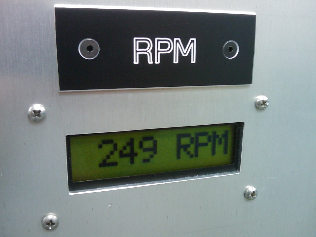
Digital RPM indicator

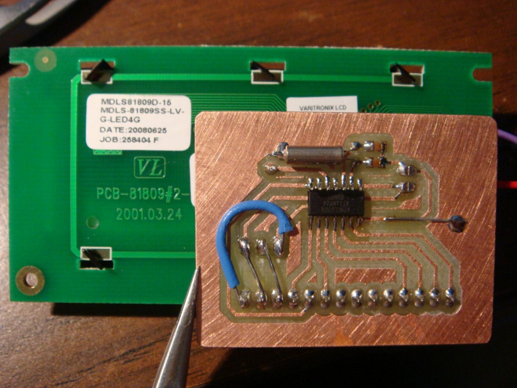
I made a circuit for RPM measurement based on an Atmel ATtiny24 to drive a Hitachi 44780 parallel interface character LCD. It uses an external interrupt request and INT0 to calculate the elapsed time between high/low transitions on the INT0 pin. The elapsed time is then converted to RPM and sent to the LCD. The code will work from RPM values up to 999, and a variable timeout is used for a low cutoff to display 0RPM. The RPM range could be extended to 9,999 or higher by modifying the decimal to BCD routine at the end of the program.

Here is the source code, it compiles with AVR Studio and AVR-GCC.
——————————————————————-
#include <avr/io.h>
#include <avr/interrupt.h>
#include <util/delay.h>

#define F_CPU 	1000000;	// 1MHz

volatile unsigned long RPM=0;	// Global RPM variable

void initLCD(void);
void lcd_write_byte(unsigned int CONTROL, unsigned int DATA);
void updateLCD(unsigned long RPM_OLD);
void check_BF(void);

void main(void)
{
TCCR1B=(1<<CS10)|(1<<CS12);	// Set up prescaler for CLK/1024
GIMSK=(1<<INT0);		// Enable external interrupt INT0
MCUCR=(1<<ISC00)|(1<<ISC01);    // Setup INT0 for rising edge detection

unsigned long RPM_OLD=1;	// Internal loop RPM variable

DDRB=0x00;			// Set PB2 for input

initLCD();			// Initialize the LCD

sei();				// Enable interrupts

while(1)
{
if((RPM != RPM_OLD) & (TCNT1 < 4000))
{
RPM_OLD=RPM;		// If new updated RPM value is not the same
updateLCD(RPM_OLD);	// as the one inside the loop, update the LCD.
}

if(TCNT1 >= 4000)	// If it's been longer than 4 seconds, RPM=0.
{
RPM=0;
if (RPM != RPM_OLD)
{
RPM_OLD=RPM;		// If new updated RPM value is not the same
updateLCD(RPM_OLD);	// as the one inside the loop, update the LCD.
}
}
}
}

ISR(EXT_INT0_vect)	// External interrupt on PB2
{
unsigned long ELAPSED;

if(TCNT1 < 4000)	// If Timer1 value is valid:
{
ELAPSED=TCNT1;		// Get Timer1 value before it changes much
TCNT1=0;		// Reset Timer1
RPM=(58594/ELAPSED);	// Calculate RPM based on Timer1 elapsed time
}

if(TCNT1 >= 4000)	// If Timer1 overflowed, value is no good.
{
TCNT1=0;		// Reset Timer1
}
}

void initLCD()
{
DDRA=0xFF;			// Set PortA for output
_delay_ms(250);			// Wait for HD44780
PORTA=0x04;			// Intialize to 4 Bit, one line
PORTA |= 0x10;
_delay_ms(1);
PORTA &= ~0x10;
_delay_ms(10);			// Intialize to 4 Bit, one line
PORTA |= 0x10;
_delay_ms(1);
PORTA &= ~0x10;
_delay_ms(10);			// Intialize to 4 Bit, one line
PORTA |= 0x10;
_delay_ms(1);
PORTA &= ~0x10;
_delay_ms(10);
lcd_write_byte(0,0x0C);		// Turn on display
lcd_write_byte(0,0x06);		// Increment by one after write

}

void lcd_write_byte(unsigned int CONTROL, unsigned int DATA)
{
// check_BF();

if(CONTROL == 1) PORTA |= 0x20; else PORTA &= ~0x20;
if((DATA & 0x80) == 0x80) PORTA |= 0x01; else PORTA &= ~0x01;
if((DATA & 0x40) == 0x40) PORTA |= 0x02; else PORTA &= ~0x02;
if((DATA & 0x20) == 0x20) PORTA |= 0x04; else PORTA &= ~0x04;
if((DATA & 0x10) == 0x10) PORTA |= 0x08; else PORTA &= ~0x08;
PORTA |= 0x10;
_delay_us(1);
PORTA &= ~0x10;

if((DATA & 0x08) == 0x08) PORTA |= 0x01; else PORTA &= ~0x01;
if((DATA & 0x04) == 0x04) PORTA |= 0x02; else PORTA &= ~0x02;
if((DATA & 0x02) == 0x02) PORTA |= 0x04; else PORTA &= ~0x04;
if((DATA & 0x01) == 0x01) PORTA |= 0x08; else PORTA &= ~0x08;
PORTA |= 0x10;
_delay_us(1);
PORTA &= ~0x10;
_delay_ms(4);
}

void updateLCD(unsigned long RPM_OLD)
{
unsigned long RPM_BCD=((((RPM_OLD/10)+((RPM_OLD/100)*6))*16)+(RPM_OLD%10));

unsigned int ONES = 0x00;
unsigned int TENS = 0x00;
unsigned int HUND = 0x00;

if((RPM_BCD & 0x0800) == 0x0800) HUND |= 0x08; else HUND &= ~0x08;
if((RPM_BCD & 0x0400) == 0x0400) HUND |= 0x04; else HUND &= ~0x04;
if((RPM_BCD & 0x0200) == 0x0200) HUND |= 0x02; else HUND &= ~0x02;
if((RPM_BCD & 0x0100) == 0x0100) HUND |= 0x01; else HUND &= ~0x01;

if((RPM_BCD & 0x0080) == 0x0080) TENS |= 0x08; else TENS &= ~0x08;
if((RPM_BCD & 0x0040) == 0x0040) TENS |= 0x04; else TENS &= ~0x04;
if((RPM_BCD & 0x0020) == 0x0020) TENS |= 0x02; else TENS &= ~0x02;
if((RPM_BCD & 0x0010) == 0x0010) TENS |= 0x01; else TENS &= ~0x01;

if((RPM_BCD & 0x0008) == 0x0008) ONES |= 0x08; else ONES &= ~0x08;
if((RPM_BCD & 0x0004) == 0x0004) ONES |= 0x04; else ONES &= ~0x04;
if((RPM_BCD & 0x0002) == 0x0002) ONES |= 0x02; else ONES &= ~0x02;
if((RPM_BCD & 0x0001) == 0x0001) ONES |= 0x01; else ONES &= ~0x01;

ONES |= 0x30;
TENS |= 0x30;
HUND |= 0x30;

lcd_write_byte(0x00, 0x01);
lcd_write_byte(0x01, 0x20);
lcd_write_byte(0x01, HUND);
lcd_write_byte(0x01, TENS);
lcd_write_byte(0x01, ONES);
lcd_write_byte(0x01, 0x20);
lcd_write_byte(0x01, 0x52);
lcd_write_byte(0x01, 0x50);
lcd_write_byte(0x01, 0x4D);

}

void check_BF(void)
{
DDRA = 0xF0;  // Set PortA 4-7 (R/W, RS, E) to output, 0-3 (DBx) for input
PORTA &= ~0x20;			// Clear register select
PORTA |= 0x40;			// Set read
PORTA |= 0x10;			// Set enable
_delay_us(1);

while((PA0 & 0x01) == 0x01)	// Read DB7 of LCD (busy flag)
{
PORTA &= ~0x10;			// Clear enable
_delay_us(1);
PORTA |= 0x10;			// Set enable
_delay_us(1);
PORTA &= ~0x10;			// Clear enable
_delay_us(1);
PORTA |= 0x10;			// Set enable
_delay_us(1);
}

PORTA &= ~0x10;			// Clear enable
_delay_us(1);
PORTA |= 0x10;			// Set enable
_delay_us(1);
PORTA &= ~0x10;			// Clear enable
PORTA &= ~0x40;			// Clear read
DDRA = 0xFF;			// Set for output

}
7 Comments to Digital RPM indicator
Leave a Reply
Other Stuff
Recent Posts
- 6CY7 dual triode valve amplifier
- Air quality sensor (TVOC and eqCO2)
- Automotive rear fill “surround sound” with Boss DD-3
- Spring tester / weight scale
- Ducati 749/999 Tail Light
- Instruments for the GSXR
- Light pipe tail light for the GSXR
- M17x 6990m / 6970m overheating
- PAR / Spectrum analyzer
- Acrylic polishing and scratch removal
Archives
- May 2019 (2)
- April 2017 (3)
- October 2015 (1)
- May 2015 (1)
- March 2014 (2)
- December 2013 (1)
- July 2013 (1)
- November 2012 (1)
- October 2012 (4)
- September 2012 (1)
- August 2012 (3)
- June 2012 (1)
- March 2012 (1)
- February 2012 (1)
- January 2012 (1)
- October 2011 (3)
- July 2011 (1)
- June 2011 (3)
- May 2011 (2)
- April 2011 (1)
- December 2010 (1)
- August 2010 (1)
- July 2010 (3)
- April 2010 (2)
- March 2010 (2)
- January 2010 (2)
- December 2009 (2)
- October 2009 (2)
- September 2009 (1)
- August 2009 (15)
You might improve your code by reading about the timer1 input capture interrupt. You may have to use a different pin. The timer can be used free running (no need to reset to 0) and the elapsed time may be calculated by the difference, using the old stored in a “static” variable in the ISR. In the ISR also set a flag that a new Elapsed is available. In the main loop, use an “if” to check the flag, then do the division at that time, and clear the flag. By moving the division from the ISR improvement happens by minimizing the ISR code. This will help you in the future as you develop more complicated systems with many interrupts and calculations.
It is also possible to do this with the external interrupt, and not have to change the pin. The advantage of the input capture is it stores the timer value for you in an ICR.
Thanks for your comment. I originally tried to use the ICP since this is what it is intended for, but I couldn’t get it to work. I can’t remember why. So I did it the less efficient way to get it done. I’m still learning a lot about programming, and most of my stuff is trial and error.
I like the idea of using a flag and checking it from the main loop. When you say “flag” I assume you mean a global variable that you toggle. I’ll try that next time!
Yes the flag is a global variable. I use CodeVision C compiler, it has bit variables. If your compiler does not support bits then a byte will do. Just set it to 1 for true, zero for false.
Your mechanical work is very nice. You have great potential. Your programming is good too. You may ask me for programming help if you need it.
I used a mega128 and built a working engine management system (fuel injection, ignition, idle speed and other controls).
You may find info here: http://my.att.net/p/s/community.dll?ep=16&ext=1&groupid=372867&ck=
Thanks Dave! I’m suitably impressed with your engine management system. I remember building an interface and hooking up my laptop to the ALDL connector on my ’88 Blazer, I was totally overwhelmed by the complexity of all of the lookup tables and how it all worked together. I’m impressed you could build that yourself. Looks good!
It has been a fun project. I was excited when it first worked. I did not sleep for a couple weeks, just to add code. You are correct, the bulk of the complexity is in all the setup information. The code that runs the engine is about 4K bytes (ISRs and calculations), the total code is about 20K bytes.
I wish the best for you with your engineering degree. It is a excellent idea. With your present knowledge and interests you will a great student. You have an advantage by having interests and energy that will help steer your career.
I’m wanting to build a 0 to 500 rpm counter for use on an 1894 steamboat.
Your Digital RPM indicator looks like what I’m wanting! Question; is it possible to get a circuit diagram of same?
You can pretty much get the schematic by looking at the picture: Use one of the AVR’s ports to run the HD44780 controller in 4-bit mode, a connector for power, and a crystal if you aren’t using the onboard oscillator.