6CY7 dual triode valve amplifier
I’ve always wanted to know what the “tube magic” was all about. There is much opinion in the science of music production, probably because music and its perception is highly personal and subjective. Ive always imagined that since transistor amplifiers were “perfect” with their large amounts of negative feedback, great linearity, and low THD that tube amplifiers must add something to sound that generates their appeal. From the reading I’ve done it has to do with harmonics.
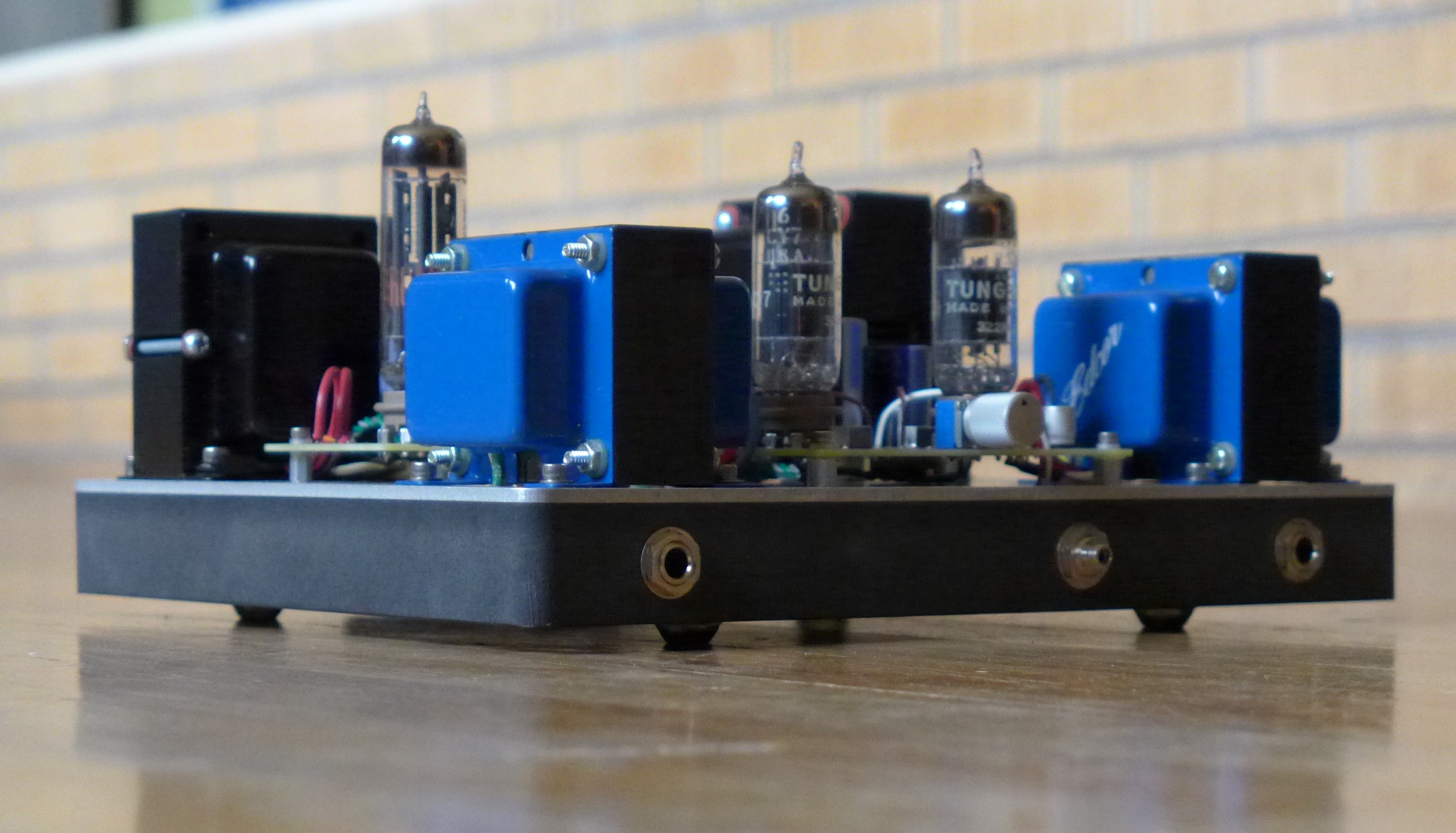
After getting back into headphones because of my kids, I decided to try building a tube amplifier that would drive my nighthawks. More specifically I wanted to build an amp that would be sort of an old school / new school hybrid, one that used circuit boards and SMT components for good EMC considerations, but had no semiconductors at all and no negative feedback.
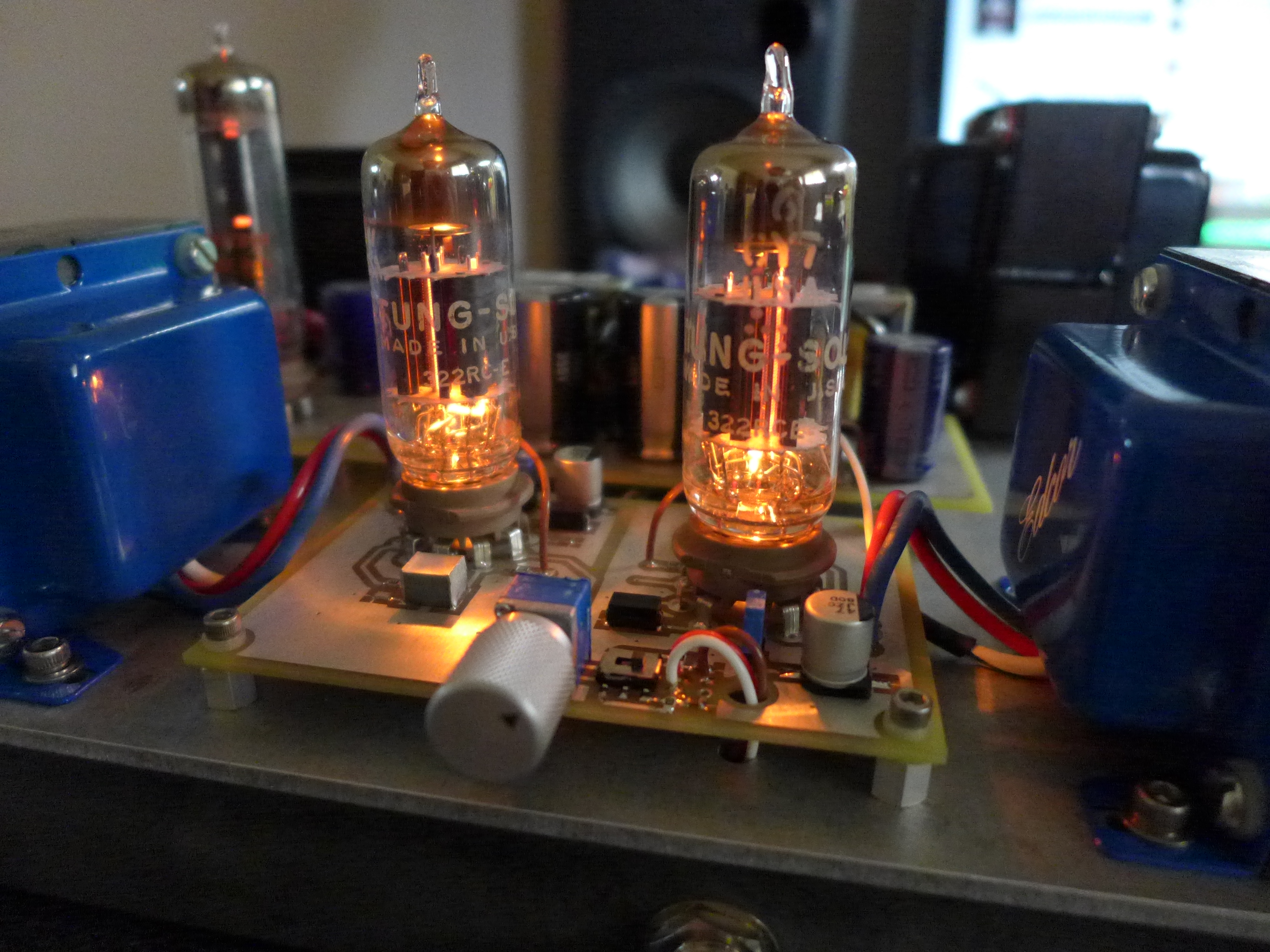
I owe much credit to Matt at cascadetubes.com, whose design of the 6CY7 amp is what I used with some modifications. This amp appealed to me not only because of the SET topology featuring no negative feedback (second stage does have degeneration), but also because the first and second amp stages for each channel were in their own tube. › Continue reading
Air quality sensor (TVOC and eqCO2)
I’ve been curious about the inexpensive gas sensors available now and whether they are useful at all. They are being built into new equipment to estimate air quality. I decided to pick one up and attach it to my K64 dev board for some hands on evaluation.
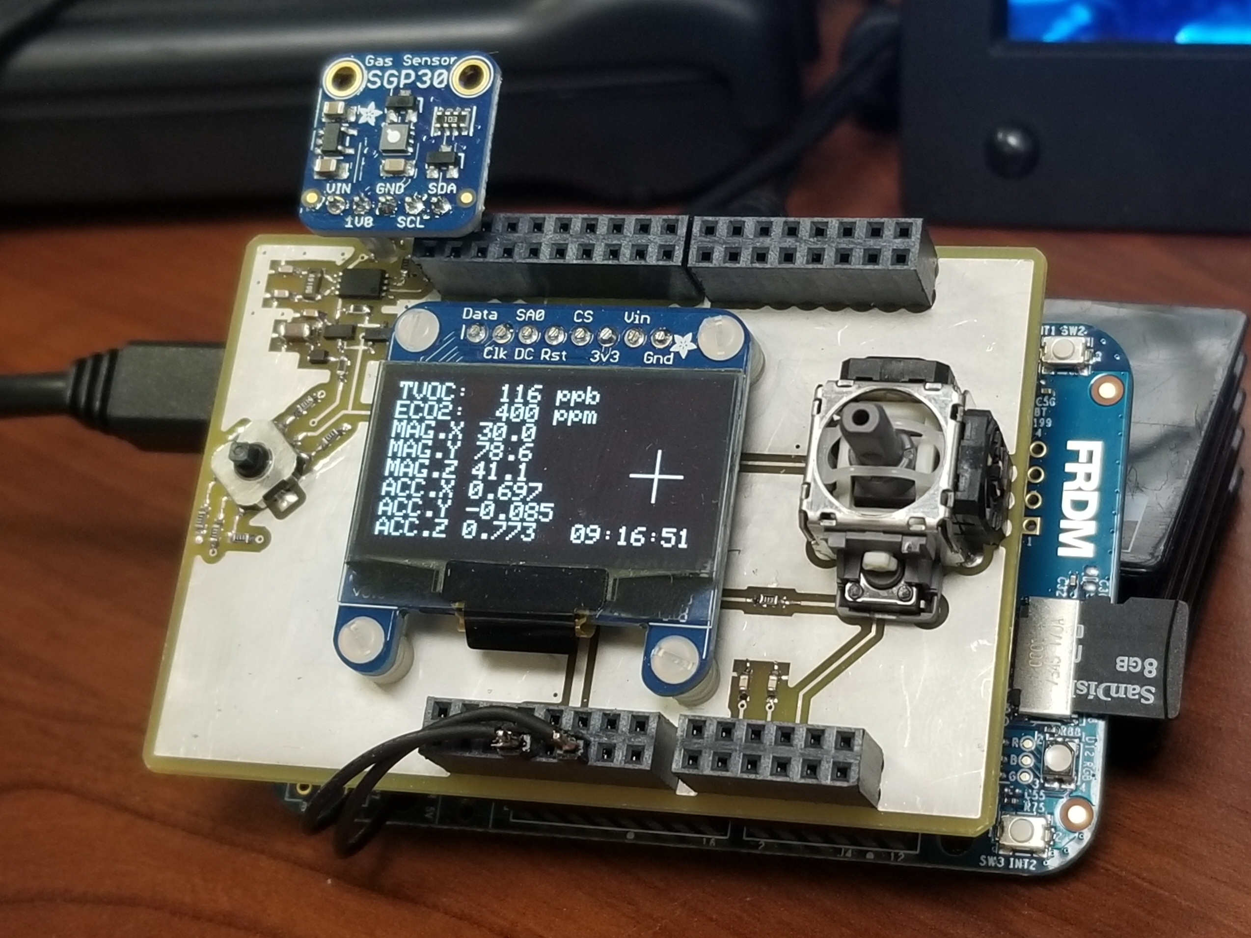
Its very responsive, but I haven’t achieved what I want to call a steady baseline. There’s an odd requirement in the datasheet to perform a measurement every second, and you can preload a baseline reference but it’s not clear exactly what you gain from that. There is also compensation for humidity but I don’t currently have that sensor. Here in Colorado its always pretty dry anyway.
At home it is usually in the 100-200ppb range for TVOC, sometimes climbing to almost 1000. I live in an older home so I guess that isn’t a surprise, however when I reset it and it turns back on sometimes the readings will be lower. At work its rarely above about 30ppb.
Sensirion has provided a nice document that describes TVOC in more detail and gives ranges for acceptable levels. It also hints that you can calibrate the sensor with ethanol but doesn’t explain how.
If anyone has used one of these and has more information on improving accuracy please leave a comment.
Automotive rear fill “surround sound” with Boss DD-3
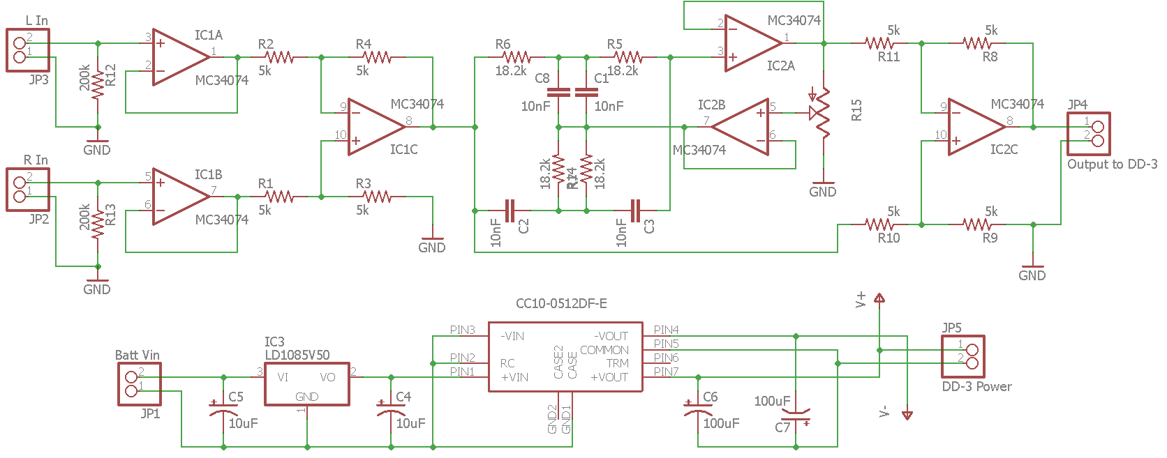
Lately I’ve been experimenting with rear fill in my car. Similar to matrix “surround sound”, but not a discrete multichannel system where sounds are meant to originate from the sides or rear; rear fill is intended to improve the front soundstage in a car which is normally pretty poor due to proximity to the left and right speakers as well as cabin reflections. Specifically this is implemented as a delayed, bandwidth limited, mono L-R difference signal for the rear speakers.
There is quite a bit of variance in implementation of this method, such as amount of delay, filter corner frequencies and Q, etc. After spending much time reading and not being confident picking some values, I decided to build a fully variable test setup.
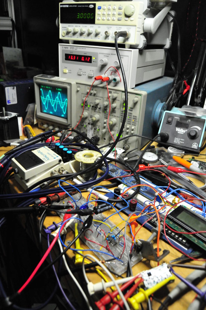
Breadboard and bench test so I don’t burn up my stereo/amps, also verifying proper operation from the DD-3.
To handle bandpass filtering and create a mono L-R difference signal I started with two op-amps to first buffer the left and right signals and then another op-amp follows as a differential amplifier to create the mono difference signal. This signal is then fed to a twin T cell notch filter with constant in-band gain but adjustable Q to provide variable bandwidth around a center frequency I chose, about 925Hz. The bandwidth of the filter is adjusted by feedback through a potentiometer without affecting gain so relative cutoff frequencies can be changed in real time. To turn the notch filter into a bandpass filter the output of the notch filter is compared to the input by a difference amplifier.
Probably the most important part of this is adding a delay. The effect relies on psychoacoustics to trick your brain into thinking you are in a bigger space since all reflections in a car are early reflections. Due to the speed of sound there just isn’t time in a car to produce late reflections which give your brain a sense of “space”. These reflections are different from echoes which the brain interprets as a separate event. The Haas effect (or precedence effect) defines that if a sound and its reflection arrive at the listener within a sufficiently short period of time the listener will perceive them as the same event. The period of time is different for different sounds, but is generally accepted to be between 20 and 30 milliseconds. The goal with rear fill is to add enough delay to simulate a larger room with later reflections but not produce an echo.
I bought a Boss DD-3 digital delay guitar pedal for this because it is perfect for the test. You can isolate just the delay signal, the delay is continuously adjustable, and one of the adjustment ranges is 12.5-50mS (which is something the MiniDSP and PT2399 can’t do). It has defeatable feedback so there will be no echo and it is digital so the signal should be accurately reproduced. It can also be instantly bypassed with the footswitch which is essential in identifying whether a change is better or worse.
› Continue reading
Spring tester / weight scale
This is another one I finished a couple months ago but haven’t posted. I wanted to test the rate of the springs in the coilover kit on my car, and manufacturers treat this like it’s some kind of trade secret. Except for a few; my kit was from Bilstein who gave me the rates but they weren’t very believable. I knew they were higher than what I was told.
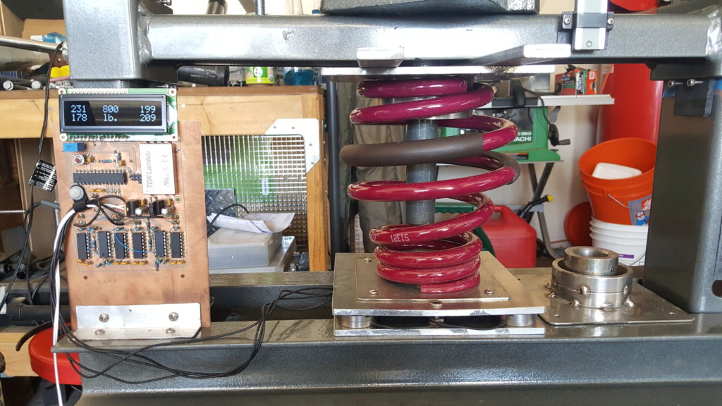
So I built a spring tester. It is basically a weigh scale that can go up to 1000 pounds or so, with a way to safely compress the spring and measure displacement. For the scale I used four load cells with one at each corner of a 1/4″ aluminum plate and another 1/4″ plate to distribute the load to the four load cells and allow fixtures for various springs. The electronics for the load cells are INA103s and some more op-amps for gain. Since load cells are bridge devices a TDK DC-DC converter drives the in-amp rails with +/- 12V. The signal from the in-amps is offset and fed to an ATmega8 which does ADC and puts the values on an LCD. I am displaying the values for each load cell as well as the sum so I can see if any load cells are not being loaded equally which could result in an overload. There is also a button on an interrupt that allows zeroing the summed weight output. › Continue reading
Ducati 749/999 Tail Light
I finished this project a while ago, but never documented it. This is a taillight I made for my 749 before I sold it. I currently have a 999 so maybe I will make another one someday, but the 999 rarely changes out of it’s track/race clothes.
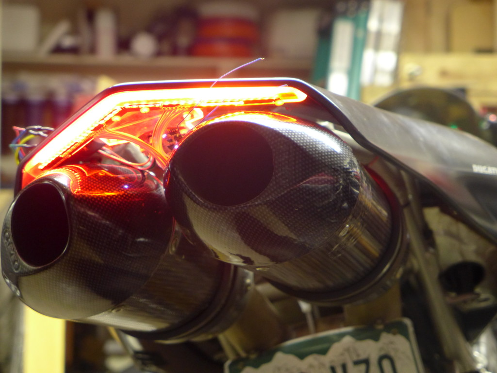
I was doing a lot of street riding when I made this, so I wanted something with better visibility than the (IMO) poor aftermarket replacement taillights. Specifically I was wanting to add a few high brightness pulses when the brake lights were turned on, but with a high enough frequency it would barely be noticeable. It catches your attention but isn’t really that obvious if you weren’t looking right at it. I’ve noticed recently that some fire trucks do this.
I’ve also been interested in a tail light with a light sensor so that the brightness can be ramped up during day time. Motorcycles need all the visibility they can get, but if the tail light gets too bright it will have the opposite effect at night and reduce visibility for people behind you. › Continue reading
Instruments for the GSXR
Since the GSXR is now a street fighter the factory gauges won’t do, and I wanted something I could log air/fuel ratios with so I can jet the bike. I went a little overboard making a new dash.
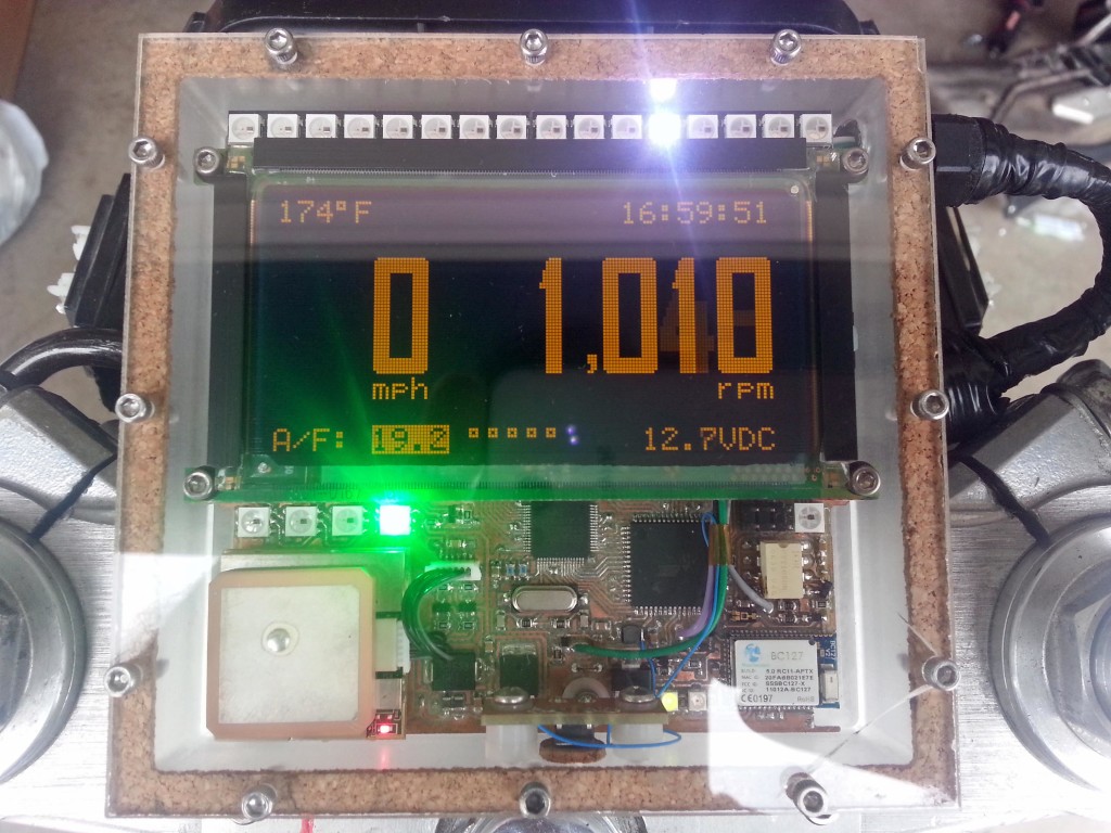
I had a Planar 160×80 EL graphic display that’s been in my parts bin for years that I’ve always wanted to use, and this was perfect. Unfortunately it doesn’t have a controller so I had to interface it to the CPU with an Epson S1D13700 graphic controller. The display indicates speed from a GPS module, air/fuel ratios from the wideband O2 sensor, engine temp, battery voltage, time from GPS, and RPM. I used a light sensor to sense ambient brightness levels and dim the display by changing TC/R in the graphics controller. The refresh of the display is high enough to allow a large dimming range without flickering. The EL display can be refreshed at up to 240Hz. The light sensor also controls the brightness of the bar graph and indicator LEDs. A BC127 bluetooth module allows datalogging via SPP, and I might eventually get around to displaying SMS messages from my phone on the display which was one of the design goals but isn’t done yet.
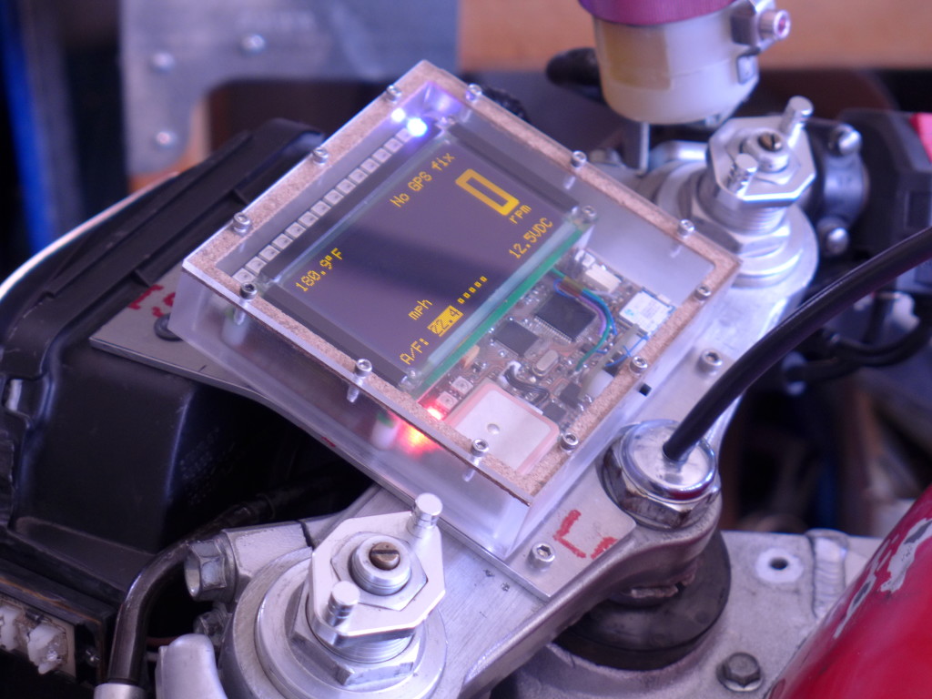
An IR optoisolator senses RPM pulses from the magnetic pickup and protects the system from ignition noise. Addressable LEDs function as indicator lights as well as forming the bar graph at the top of the display. The bar graph can display RPM, battery voltage, engine temp, or A/F ratios depending on the current mode which is selected by a button on the side of the housing. The bar graph is also a two stage shift light which overrides any display mode and goes to full brightness with two different colors to indicate high RPM for shifting. A highlight box on the graphics layer shows which mode is currently active and the graphic and text layers are XOR’ed. I also made a custom bitmapped font I thought went well with the display size and the amount of characters.
› Continue reading
Light pipe tail light for the GSXR
I wanted the new subframe and tail of my GSXR to be really different, I wanted a kind of rough raw look but still really clean. I used unfinished stainless steel and some really angular sections to achieve this. One of the most important parts about how I built the tail was being able to add a light pipe around the outside perimeter for a taillight.
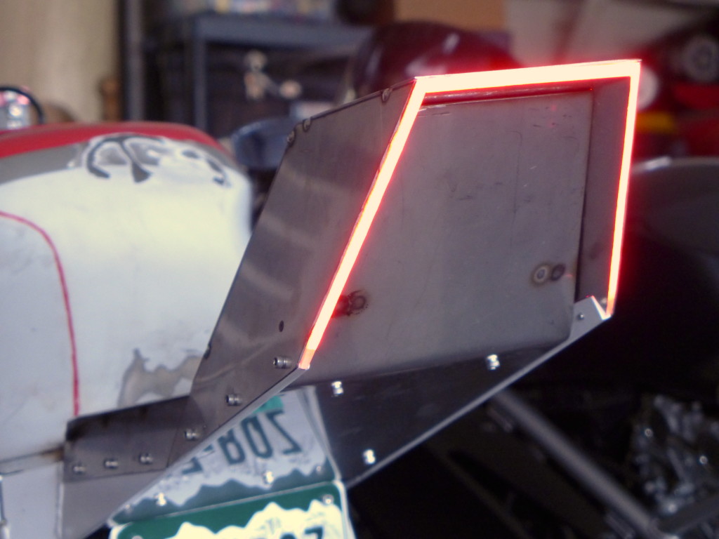
I made the light pipe from 1/4″ acrylic, cut out three sections and used acrylic cement to join them. I added LEDs and coupled them to the light guide with LOCA glue. The amount of LEDs I had to use to achieve good brightness meant I would need to build a boost power supply for the LED drivers since the strings would require more than the available voltage. Here is a simple boost power supply I made with three LED drivers and an ATtiny2313 for controlling flashing the side segments as turn signals. There was some logic required to sense the turn signal state prior to the switch and keep the sides working correctly as both brake and signals.
› Continue reading
M17x 6990m / 6970m overheating
How to fix AMD 6900 series cards overheating in the Alienware M17x. › Continue reading
PAR / Spectrum analyzer
I’ve been working on an off for a while on a project to measure photosynthetically active radiation (PAR) as well as analyze electromagnetic spectrum with the same sensor, at the same time. The spectrum in question is approximately 350-750nm. I mainly envisioned this tool for use with marine aquariums, and if things were going better I probably would have built a prototype.
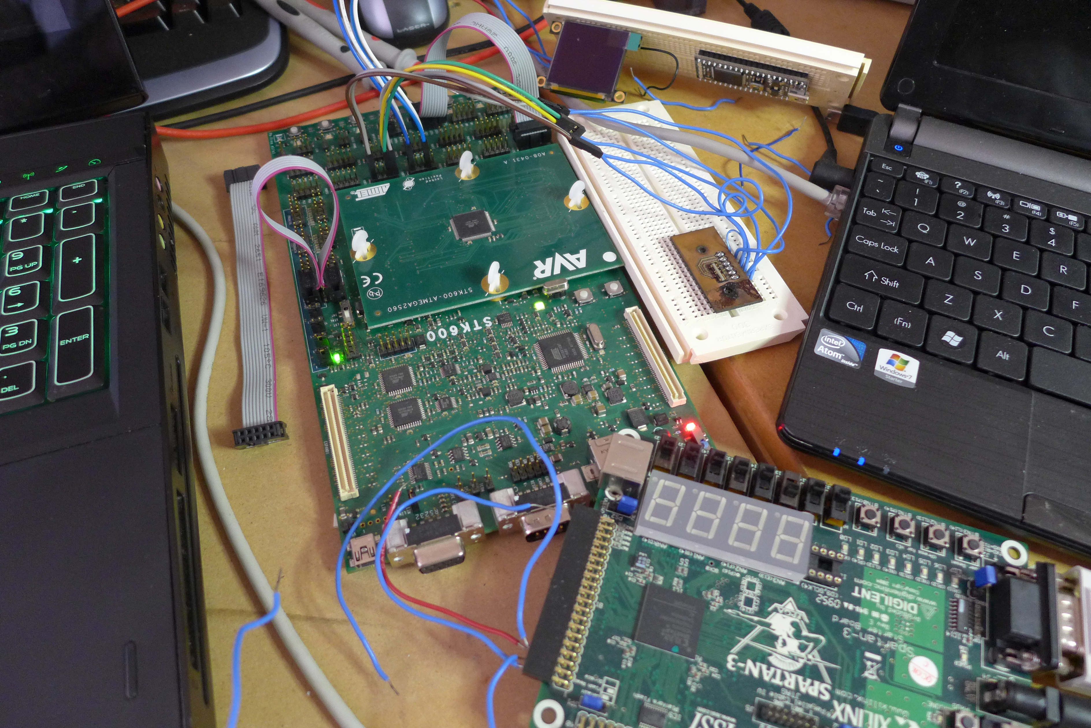
The sensor is a TAOS TSL3301CL. It is a 102-pixel photodiode array with a serial interface. The sensor contains analog stages for gain and offset as well as ADCs that sample the values and read the results to the serial port. It’s a nice device, but I haven’t been able to get what I want out of it. The response for me has been very non-linear. It’s also a very tiny leadless package so it’s not easy to work with.
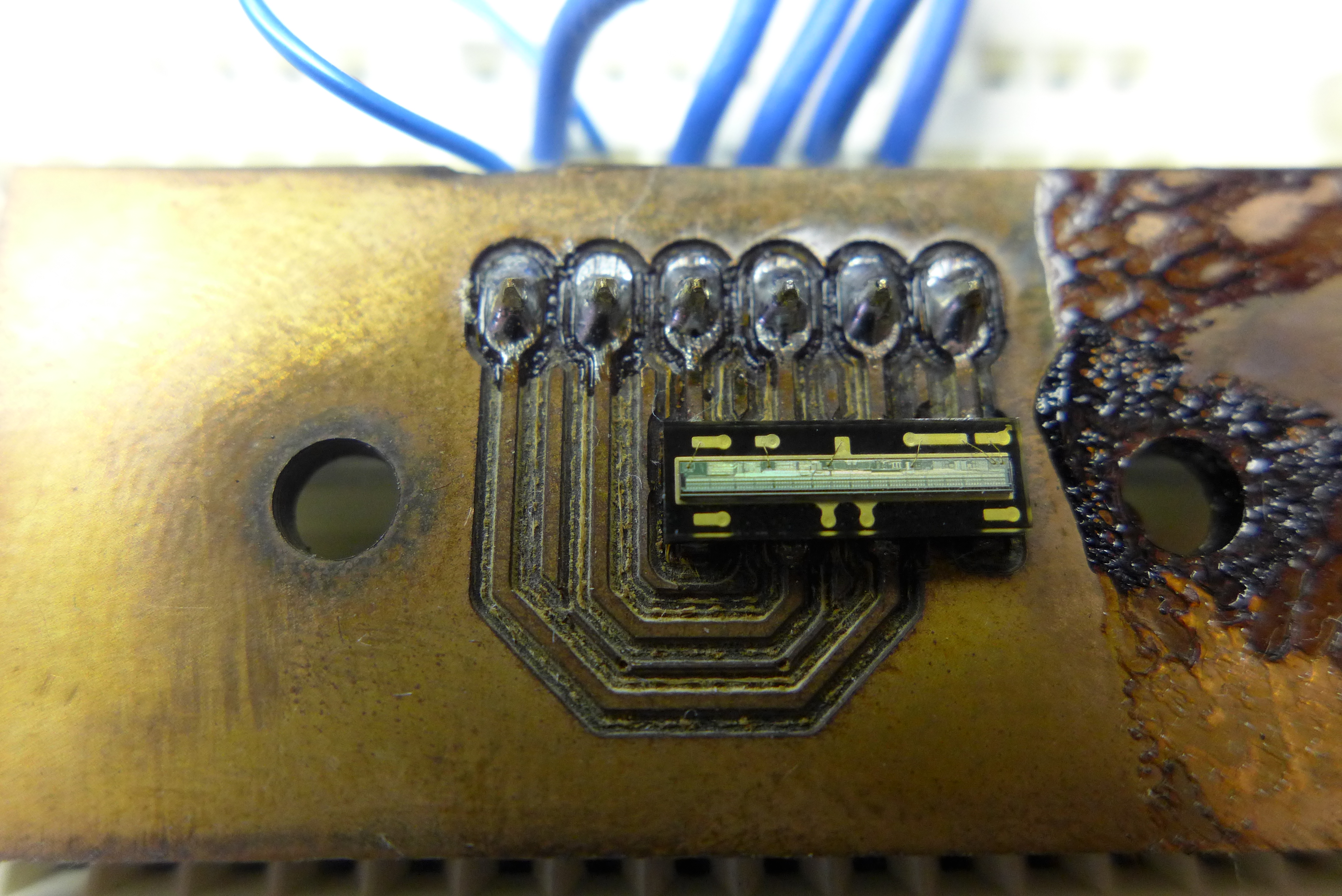
For reference, that is a 0.1″ header
My plan was to enclose the sensor in a housing with a series of lenses designed to introduce chromatic aberration or a prism to refract the captured ambient light, and then direct the spectral components of the light towards the sensor. The sensor’s response to wavelength is non-linear, but that can be corrected with a function in software for each pixel.
I had a uOLED 128×128 pixel display that I used to display the intensity of light for each pixel. This worked well, and I would have used an averaging function to estimate PAR from that data.
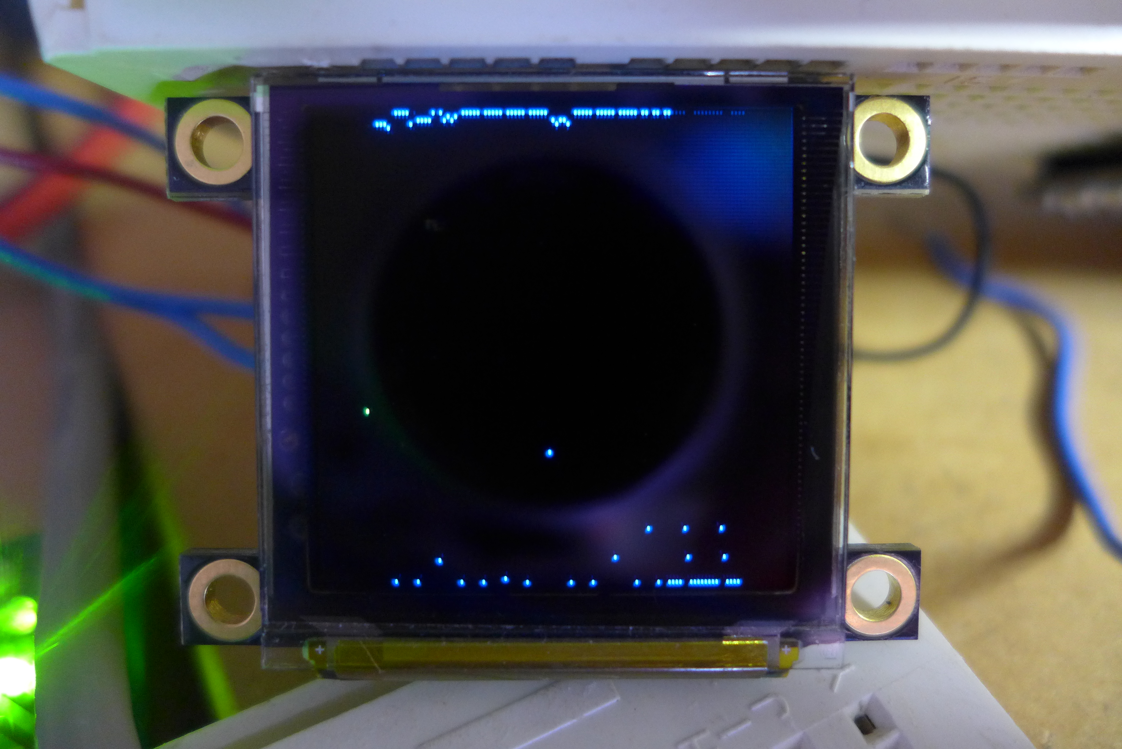
However, I haven’t been able to get the sensor to respond in what I consider a linear fashion. It is mostly on or off. Moving the light source back and forth from the sensor doesn’t result in any gradient that could be considered measurable. I’ve tried various gain and offset levels, as well as long and short integration times but with no success.
I originally tested it with an mbed, but I had trouble with the sensor’s synchronous clock. So I ported the code to the mega2560 on my STK600. About that time the display started to die and I don’t have another graphic display at the moment without messing around with an Epson S1D1335 and another graphics library… As such I’m stashing this project for now. If anyone has worked with these sensors before and knows what I’m doing wrong, I’d like to hear from you.
Acrylic polishing and scratch removal
I recently acquired a 46 gallon ZeroEdge aquarium that was in pretty rough shape. There were a lot of scratches as well as marks from calcareous algae. Here is what I did to repair it. › Continue reading
Other Stuff
Recent Posts
- 6CY7 dual triode valve amplifier
- Air quality sensor (TVOC and eqCO2)
- Automotive rear fill “surround sound” with Boss DD-3
- Spring tester / weight scale
- Ducati 749/999 Tail Light
- Instruments for the GSXR
- Light pipe tail light for the GSXR
- M17x 6990m / 6970m overheating
- PAR / Spectrum analyzer
- Acrylic polishing and scratch removal
Archives
- May 2019 (2)
- April 2017 (3)
- October 2015 (1)
- May 2015 (1)
- March 2014 (2)
- December 2013 (1)
- July 2013 (1)
- November 2012 (1)
- October 2012 (4)
- September 2012 (1)
- August 2012 (3)
- June 2012 (1)
- March 2012 (1)
- February 2012 (1)
- January 2012 (1)
- October 2011 (3)
- July 2011 (1)
- June 2011 (3)
- May 2011 (2)
- April 2011 (1)
- December 2010 (1)
- August 2010 (1)
- July 2010 (3)
- April 2010 (2)
- March 2010 (2)
- January 2010 (2)
- December 2009 (2)
- October 2009 (2)
- September 2009 (1)
- August 2009 (15)