CNC
Ducati 749/999 Tail Light
I finished this project a while ago, but never documented it. This is a taillight I made for my 749 before I sold it. I currently have a 999 so maybe I will make another one someday, but the 999 rarely changes out of it’s track/race clothes.
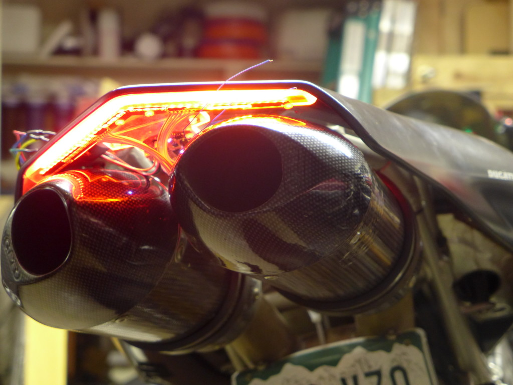
I was doing a lot of street riding when I made this, so I wanted something with better visibility than the (IMO) poor aftermarket replacement taillights. Specifically I was wanting to add a few high brightness pulses when the brake lights were turned on, but with a high enough frequency it would barely be noticeable. It catches your attention but isn’t really that obvious if you weren’t looking right at it. I’ve noticed recently that some fire trucks do this.
I’ve also been interested in a tail light with a light sensor so that the brightness can be ramped up during day time. Motorcycles need all the visibility they can get, but if the tail light gets too bright it will have the opposite effect at night and reduce visibility for people behind you. › Continue reading
Instruments for the GSXR
Since the GSXR is now a street fighter the factory gauges won’t do, and I wanted something I could log air/fuel ratios with so I can jet the bike. I went a little overboard making a new dash.
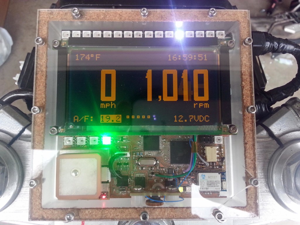
I had a Planar 160×80 EL graphic display that’s been in my parts bin for years that I’ve always wanted to use, and this was perfect. Unfortunately it doesn’t have a controller so I had to interface it to the CPU with an Epson S1D13700 graphic controller. The display indicates speed from a GPS module, air/fuel ratios from the wideband O2 sensor, engine temp, battery voltage, time from GPS, and RPM. I used a light sensor to sense ambient brightness levels and dim the display by changing TC/R in the graphics controller. The refresh of the display is high enough to allow a large dimming range without flickering. The EL display can be refreshed at up to 240Hz. The light sensor also controls the brightness of the bar graph and indicator LEDs. A BC127 bluetooth module allows datalogging via SPP, and I might eventually get around to displaying SMS messages from my phone on the display which was one of the design goals but isn’t done yet.
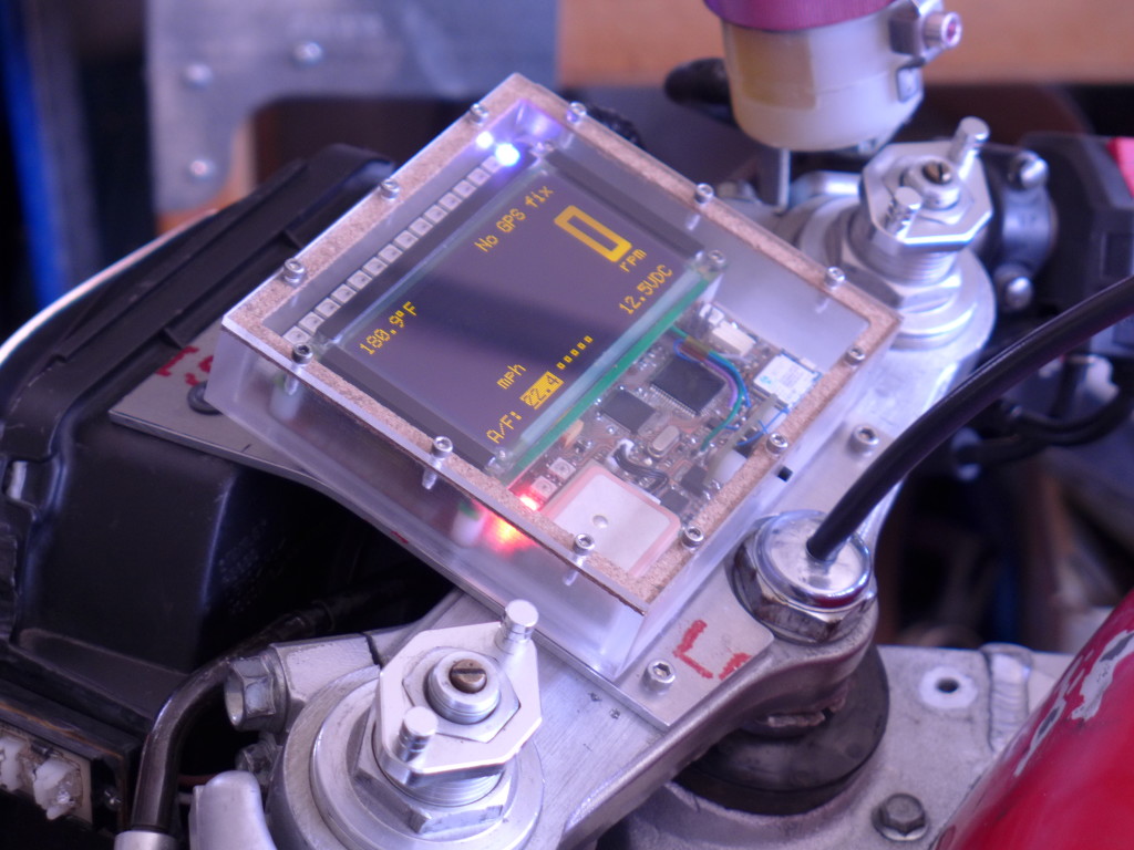
An IR optoisolator senses RPM pulses from the magnetic pickup and protects the system from ignition noise. Addressable LEDs function as indicator lights as well as forming the bar graph at the top of the display. The bar graph can display RPM, battery voltage, engine temp, or A/F ratios depending on the current mode which is selected by a button on the side of the housing. The bar graph is also a two stage shift light which overrides any display mode and goes to full brightness with two different colors to indicate high RPM for shifting. A highlight box on the graphics layer shows which mode is currently active and the graphic and text layers are XOR’ed. I also made a custom bitmapped font I thought went well with the display size and the amount of characters.
› Continue reading
Upgrade M17x R1 to R2 motherboard
I have an Alienware M17x that has the Core 2 Quad processor. This isn’t a bad setup, but an i7 in the R2 is much better. There is also the restriction that the R1 can only run the GTX 260m, 280m or AMD 5870m. This makes the M17x mostly obsolete for any modern games. I tried quite a few things to get an AMD 6970m running in the R1 (see here), including modifying the MXM structure in the BIOS. I wasn’t successful, mostly because I eventually figured out that the card I got off eBay to test with was bad. However, I did figure out that an R2 motherboard can replace the R1 motherboard. You will of course need a new processor and the CPU/southbridge is in a different location so you also need an R2 heatsink. Everything else is compatible, and the R2 will run the 6970m.
The only things I had to modify was the LVDS link width for the R1 LCD and the magnesium plate that covers the motherboard. Since the heatsink is in a different location you need to relieve a couple spots.

For the LVDS connection the BIOS for the R2 specifies a 24-bit width and the R1 is an 18-bit width. I modified the MXM system info in the BIOS to fix that and updated the checksum. Then I flashed it to the motherboard. I did this before I figured out the 6970m was dead, so I don’t know if the R1 LCD will work or not without running a modified BIOS since it never POSTed and I fixed the card after flashing the BIOS. › Continue reading
CNC version 2.0
I finally finished putting together my second CNC machine. Again this one is put together with surplus parts, but they are much better surplus parts. I have the luxury of three linear slides from Newmark Systems, that have dual profile rails and recirculating ball slides, along with 16TPI precision screws and recirculating ball guides. In short, the new machine is solid as a rock, and has more torque.

PCB layouts and schematics for my CNC
I’ve received some email and comment requests for the layouts and schematics of the electronics running my CNC machine. I’ve pulled together what I can find for this article.
Power Filter Boards

I made these power filters for a few reasons. One is to protect the stepper motor drives from the inductive spikes that can come off of the motors. They can be pretty big. Another reason was that I wanted to use a switch-mode power supply to run the drives. There’s a lot of good reasons for this:
1. Switch-mode power supplies are cheaper than linear power supplies.
2. Switch-mode power supplies are smaller than linear supplies for equivalent output power.
3. Switch-mode power supplies come in a wide range of voltages, so you can run the stepper motors at the highest voltage possible. (The highest voltage your controller supports) This allows for more torque from any motor because a higher voltage will push more current through the inductance of the motor than a lower voltage. It will also do it quicker, so you should get a little more speed too.
However, I wasn’t sure that the chopper-style stepper driver would be okay with a switch mode supply, as it pretty much shorts out the supply every time the chopper turns on. So I needed a buffer.
I found this article at EETimesAsia by John Betten from TI. I modified the circuit for the voltage levels I wanted to run, and also found a suitable replacement for the FET since I couldn’t find one at the time. Here is the original schematic:

I’m using an IR IRFP9140N in place of Q1. I also replaced D2 with a 56V TVS from ON semi, 1.5KE56A. I used 56V because the LMD18245 motor driver IC I have has a continuous rating of 55V and an absolute max of 60V. I also oversized the output capacitor just to be on the safe side since I had some big ones laying around anyway. They are 22000uF 100V Panasonics. They are overkill, the voltage is rock-solid even when the motors are running at full clip. I wanted to be able to recycle the boards though if I ever upgrade to a bigger machine and have bigger motors. Here’s the layout for my circuit:

Opto-isolated Parallel Interface Board
I designed this parallel interface board after killing a parallel port with a breakout board that I bought off the internet. I think it just pulled too much current from the port. I designed this board to pull the smallest amount of current from the parallel port as possible, while also providing good drive characteristics for outputs. This board is customized to my application, so the voltages and bias might not be appropriate for all. Check to make sure your inputs will work before using the values here. I couldn’t find the schematic, just the layout but it’s not too complicated to figure out if you have the datasheets for the TLP2631 and the SN74LS244N. › Continue reading
0.008″ PCB trace isolation on my CNC
Due to a new design that I am working on, I needed to use a component from TI that only came in a 6SC70 package. It’s a boost converter (TPS61221) that operates from an input voltage as low as 0.7V and has 80% or better efficiency in the 1-10mA range. It’s trimmed at 3.3V, which I’m using to run an ATtiny45V. The ATtiny45 comes in a fine-pitch package as well, an 8TSSOP that requires 0.009″ isolation between pads. I haven’t been able to get much better than 0.020″ with the tooling I have, so I have been looking for alternatives.
I found some mechanical engraving bits at Think & Tinker which is actually here in Colorado at Palmer Lake. Their URL descriptor says they offer “Instrument and PCB prototyping equipment”. They also sell carbide engraving bits, and the particular one I selected was the 60° cutter, part number #EM2E8-0625-60V. The bits came in a nice container and are labelled as having a 0.005″ tip. The shipping was also wicked fast. Granted, it’s only a few hours away from my location but I ordered them and got them in the next day.

I’ve only cut one board, but I’m really happy with the results. I successfully achieved 0.008″ isolation between the pads of the devices, and now I can finally route traces inbetween the pads of 0.1″ headers. I couldn’t do that before.

My homebuilt CNC machine
I finally assembled enough surplus parts and scrap material to build a halfway decent CNC machine. I have been looking forward to actually completing this task for some time, but the appropriate parts and materials are prohibitively expensive for the individual on a budget. This spring I managed to complete the project.
Most of the machine is made out of either aluminum or acrylic. These materials are both easy to work with when all you have available is various hand tools and a drill press with a cross slide vise. The motors are NEMA 23 high torque, the threaded rods are 1/2-10 precision ACME and the nuts are anti-backlash. This results in pretty decent X-Y movement. I made the slides from extruded aluminum profiles available at the hardware store and some strips of Teflon.

I made all of the electronics that support the machine. I made the optical home and limit switches, as well as both parallel port interface boards. I also assembled the stepper motor drivers and built power filters/regulators for the input to the stepper motor drives on all three axes. This prevents inductive feedback spikes from the motors ruining the stepper motor control ICs. I need this because I’m running the motors at 48VDC and the controller IC has an absolute maximum voltage rating of 60VDC. I also wanted to keep any switching noise and voltage dips from the switch-mode power supply out of the stepper drives. Each filter has a FET-regulated output that clamps the voltage and then sends it out to some big capacitors to prevent the voltage from dropping.
The parallel interface boards completely isolate the controlling PC from the drives and other electronics. Buffers handle all the appropriate levels and opto-isolators keep the ports safe.

I’ve run it extensively with TurboCNC, but I don’t get any of the limit and home functionality because TurboCNC only supports legacy port addresses, and most parallel port PCI cards can’t map to legacy addresses. This leaves me with only the one on-board parallel port, which is mostly used up by the 3 axis step and direction signals. It works in Mach3 CNC, but I can’t afford to buy that program right now. So I’ve used it in evaluation mode for doing simple text engraving on plastics and acrylic. Oddly enough I couldn’t get it to work at all in Mach2. The pulse train output to the stepper drives was inconsistent enough that the motors would stall. I even tried it on a few different computers, one of which was a brand new XP install.
The machine mostly cranks out PC boards thanks to Eagle CAD and PCB2GCode. I’ve made quite a few since the machine was finished. It does a pretty good job, and holds flatness to a couple thousandths. It’s enough to get routine 0.020″ isolation on traces and pads, and clean 0.012″ trace widths. It’s a bit slow because of the low-buck slides, the motors stall if I speed it up much. It’s not exactly a high precision machine, so I can live with slow.
I’ve got some better parts since I built this one, and I’m planning on building another one with much better accuracy in the near future. This machine won’t handle the fine traces necessary to make boards with the newer components.
Here’s a video of the machine in action:
You can see more videos at youtube: imsolidstate’s CNC machine
Other Stuff
Recent Posts
Archives
- May 2019 (2)
- April 2017 (3)
- October 2015 (1)
- May 2015 (1)
- March 2014 (2)
- December 2013 (1)
- July 2013 (1)
- November 2012 (1)
- October 2012 (4)
- September 2012 (1)
- August 2012 (3)
- June 2012 (1)
- March 2012 (1)
- February 2012 (1)
- January 2012 (1)
- October 2011 (3)
- July 2011 (1)
- June 2011 (3)
- May 2011 (2)
- April 2011 (1)
- December 2010 (1)
- August 2010 (1)
- July 2010 (3)
- April 2010 (2)
- March 2010 (2)
- January 2010 (2)
- December 2009 (2)
- October 2009 (2)
- September 2009 (1)
- August 2009 (15)