PCB
Spring tester / weight scale
This is another one I finished a couple months ago but haven’t posted. I wanted to test the rate of the springs in the coilover kit on my car, and manufacturers treat this like it’s some kind of trade secret. Except for a few; my kit was from Bilstein who gave me the rates but they weren’t very believable. I knew they were higher than what I was told.
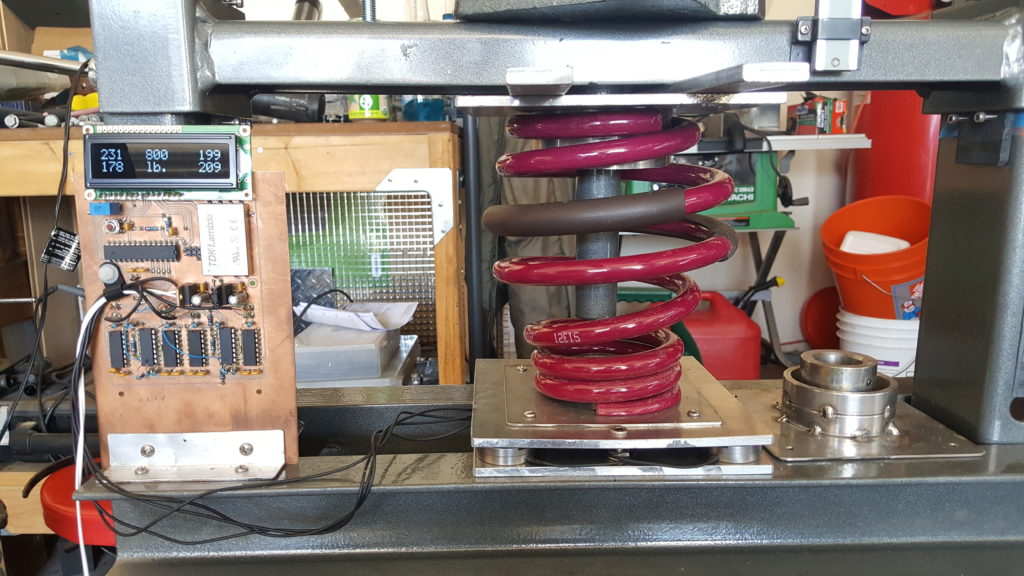
So I built a spring tester. It is basically a weigh scale that can go up to 1000 pounds or so, with a way to safely compress the spring and measure displacement. For the scale I used four load cells with one at each corner of a 1/4″ aluminum plate and another 1/4″ plate to distribute the load to the four load cells and allow fixtures for various springs. The electronics for the load cells are INA103s and some more op-amps for gain. Since load cells are bridge devices a TDK DC-DC converter drives the in-amp rails with +/- 12V. The signal from the in-amps is offset and fed to an ATmega8 which does ADC and puts the values on an LCD. I am displaying the values for each load cell as well as the sum so I can see if any load cells are not being loaded equally which could result in an overload. There is also a button on an interrupt that allows zeroing the summed weight output. › Continue reading
CNC version 2.0
I finally finished putting together my second CNC machine. Again this one is put together with surplus parts, but they are much better surplus parts. I have the luxury of three linear slides from Newmark Systems, that have dual profile rails and recirculating ball slides, along with 16TPI precision screws and recirculating ball guides. In short, the new machine is solid as a rock, and has more torque.

Pressure mapping with DIY foam load cells
I had an idea a while back to make a pressure sensing pad for testing saddle fit on horses. The intent was to create an array of pressure sensing cells, which could then be used to produce a pressure map that would represent any pinch points on a horse’s back. I found that you can buy this sort of thing, but it’s way too expensive for the average guy. I decided to try and make my own for cheap. I ended up making one from a handful of copper-clad PCBs and 1/4″ shipping foam.

The active area of the pad is approximately 2′ x 2′. I think the foam is polyurethane open-cell foam but I’m not sure. It’s the stuff you use to pack shipping crates. The load cells are made by sandwiching the foam in between 1″ circle cutouts of copper-clad FR4 PC board. I used single sided board and a hole saw with the pilot bit removed (use a drill press and a clamp). The capacitance varies as the foam compresses, and the amount of capacitance is directly related to the thickness and density of the foam, as well as the area of the copper conductors (plates). So you can create any size or thickness load cell you want really. A bigger plate results in more capacitance, as does placing the plates closer together. I estimated the capacitance I would have in my application with this calculator I found at Daycounter engineering services.
I created an array of 64 cells by making 8 rows and 8 columns, each with 8 copper-clad discs. Wherever the row/column discs align a load cell is created. An AVR typically has eight available ADC inputs along with another eight control outputs, so this way you can scan down through the rows and columns to measure each cell. A square wave is sequentially output on the columns, and after some analog proccessing the AVR’s ADC scans each row. The analog voltage present represents the amount of pressure (capacitance) at each site. › Continue reading
SMS remote control
I’ve been expirimenting with cheap GSM cell phones as remote control devices. I wanted to be able to control stuff at my house just by sending a text from my phone. I also wanted to use an AVR since the options are pretty limitless as to what you can control. I started off simple with relay outputs for stuff like the garage door, outside lights, etc. It could also be useful for the AVR to send texts based on events, but I haven’t messed with this yet.

I planned on just having the AVR recognize a particular text string, like “open garage” if I wanted to let someone in my house when I’m not there without giving them a key for example. It’s not overly secure, but you could add a number sequence as a prefix to the command that would be like a password. Then you could periodically change your password if you wanted. › Continue reading
PCB layouts and schematics for my CNC
I’ve received some email and comment requests for the layouts and schematics of the electronics running my CNC machine. I’ve pulled together what I can find for this article.
Power Filter Boards

I made these power filters for a few reasons. One is to protect the stepper motor drives from the inductive spikes that can come off of the motors. They can be pretty big. Another reason was that I wanted to use a switch-mode power supply to run the drives. There’s a lot of good reasons for this:
1. Switch-mode power supplies are cheaper than linear power supplies.
2. Switch-mode power supplies are smaller than linear supplies for equivalent output power.
3. Switch-mode power supplies come in a wide range of voltages, so you can run the stepper motors at the highest voltage possible. (The highest voltage your controller supports) This allows for more torque from any motor because a higher voltage will push more current through the inductance of the motor than a lower voltage. It will also do it quicker, so you should get a little more speed too.
However, I wasn’t sure that the chopper-style stepper driver would be okay with a switch mode supply, as it pretty much shorts out the supply every time the chopper turns on. So I needed a buffer.
I found this article at EETimesAsia by John Betten from TI. I modified the circuit for the voltage levels I wanted to run, and also found a suitable replacement for the FET since I couldn’t find one at the time. Here is the original schematic:

I’m using an IR IRFP9140N in place of Q1. I also replaced D2 with a 56V TVS from ON semi, 1.5KE56A. I used 56V because the LMD18245 motor driver IC I have has a continuous rating of 55V and an absolute max of 60V. I also oversized the output capacitor just to be on the safe side since I had some big ones laying around anyway. They are 22000uF 100V Panasonics. They are overkill, the voltage is rock-solid even when the motors are running at full clip. I wanted to be able to recycle the boards though if I ever upgrade to a bigger machine and have bigger motors. Here’s the layout for my circuit:

Opto-isolated Parallel Interface Board
I designed this parallel interface board after killing a parallel port with a breakout board that I bought off the internet. I think it just pulled too much current from the port. I designed this board to pull the smallest amount of current from the parallel port as possible, while also providing good drive characteristics for outputs. This board is customized to my application, so the voltages and bias might not be appropriate for all. Check to make sure your inputs will work before using the values here. I couldn’t find the schematic, just the layout but it’s not too complicated to figure out if you have the datasheets for the TLP2631 and the SN74LS244N. › Continue reading
Build a spot welder from a battery charger
I ran across a battery charger a while ago that was collecting dust. I looked inside and saw the transformer, heatsinks, high current bridge rectifier and SCR and knew I could do something with it. So I turned it into a spot welder.

I originally intended this project to weld thin sheetmetal tabs to stuff to act as solder tabs. The project has not been as easy as I originally thought though. (It also suffered some scope creep) It’s my first crack at 5V logic mixed with line AC voltage, and for rolling my own power supply. I used a step-down transformer, bridge regulator and a capacitor to feed an LDO regulator for the control circuit. With the low current draw of the controller, the voltage input to the regulator was relatively free from any ripple thanks to the capacitor.
I ended up frying a processor, LCD, and a couple other components due to a dumb move while troubleshooting the circuit, and overlooking a capacitor’s voltage rating. 120VAC will eat 5V stuff for lunch.

The control circuit basically modulates the SCR, which is hooked up to the output of the bridge rectifier after a step-down transformer. The controller allows for adjustment of duration of the weld and amount of the rectified AC phase that is delivered to the workpiece. The controller holds off the SCR until a pre-determined time of each half phase to control power delivery. An analog comparator detects the zero point of the phase for timing purposes, via a seperate bridge rectifier that has it’s ouput fed through a large resistor to the comparator. A zener clamps the current-limited voltage at 4.8V so as not to damage the micro’s input. A high-to-low transition on the comparator triggers the zero crossing timer. The threshhold voltage is adjustable by an on-board pot.
I also added an Allegro hall effect current sensor that I had lying around from my alternator current sense project. It’s overkill, but it measures the amount of peak current being delivered and displays it on the LCD.

The controller is an ATmega88PA running at 8Mhz. Firmware is written in C with AVRStudio and AVR-GCC. The micro reads the power and duration settings, displays that on the LCD, along with the max current for the last weld cycle and the temperature of the mega’s on-chip sensor. The controller also handles timing duties, zero crossing detection, and control of the SCR gate. The gate is fired by a P-channel MOSFET, with the FET’s gate driven by an NPN BJT on one of the micro’s pins. A footswitch is used as input to the micro to trigger a weld cycle. Both the footswitch input and the zero crossings are buffered by a simple three-sample debouncing routine to prevent erroneous triggers. The system also checks for the footswitch input on power up and after the weld cycle is complete, and waits if the footswitch is down with a message on the LCD to release the footswitch. This allows for safety as well as eliminating any unintended re-triggers at very short durations. Duration is adjustable from roughly one ac cycle to 60 cycles (1 sec). Power control allows from 5% to 95% of each half phase to be delivered to the workpiece.
The SCR’s cathode voltage is available at PORTC2 as a 10:1 voltage divider, and clamped with a zener to prevent damage to the micro. I didn’t need it, so it’s not used in the code.
I’ve also added a power resistor to the output to limit current. I used carbon-carbon as a power resistor (I work in a carbon plant) since it’s free and power resistors are expensive. You only need a few tenths of an ohm to limit the current to a level that won’t destroy the diodes and SCR. I’m overdriving mine at about 130A maximum. It seems to handle it fine for the short bursts. [Edit: 130A isn’t enough though. I may rewire so the diodes/SCR are on the input side and push the current higher by removing or modifying the resistor. Pressure of the electrodes on the joint is also important, still figuring that out.]
Here’s some drive waveforms: yellow is the output voltage (it’s at 50V/div so it looks small), purple is the output current measured by the hall sensor, blue is the FET’s gate that turns on the SCR, and green is the bridge voltage.


This project has got me thinking about modifying my old “buzzbox” AC welder. I’ve got some big capacitors and IGBTs from a couple old motor drives that could give me a really nice TIG welding power supply. I think I’ve read you can weld high frequency (1-2kHz?) square-wave without needing any HF section. If I remember right square-wave with a positive DC offset is sort of the ultimate TIG welder. Anybody with comments or information about that feel free to drop me a line.
Continue reading for the schematic, PCB layout, and code.
References: Miller Resistance Spot Welding
0.008″ PCB trace isolation on my CNC
Due to a new design that I am working on, I needed to use a component from TI that only came in a 6SC70 package. It’s a boost converter (TPS61221) that operates from an input voltage as low as 0.7V and has 80% or better efficiency in the 1-10mA range. It’s trimmed at 3.3V, which I’m using to run an ATtiny45V. The ATtiny45 comes in a fine-pitch package as well, an 8TSSOP that requires 0.009″ isolation between pads. I haven’t been able to get much better than 0.020″ with the tooling I have, so I have been looking for alternatives.
I found some mechanical engraving bits at Think & Tinker which is actually here in Colorado at Palmer Lake. Their URL descriptor says they offer “Instrument and PCB prototyping equipment”. They also sell carbide engraving bits, and the particular one I selected was the 60° cutter, part number #EM2E8-0625-60V. The bits came in a nice container and are labelled as having a 0.005″ tip. The shipping was also wicked fast. Granted, it’s only a few hours away from my location but I ordered them and got them in the next day.

I’ve only cut one board, but I’m really happy with the results. I successfully achieved 0.008″ isolation between the pads of the devices, and now I can finally route traces inbetween the pads of 0.1″ headers. I couldn’t do that before.

My homebuilt CNC machine
I finally assembled enough surplus parts and scrap material to build a halfway decent CNC machine. I have been looking forward to actually completing this task for some time, but the appropriate parts and materials are prohibitively expensive for the individual on a budget. This spring I managed to complete the project.
Most of the machine is made out of either aluminum or acrylic. These materials are both easy to work with when all you have available is various hand tools and a drill press with a cross slide vise. The motors are NEMA 23 high torque, the threaded rods are 1/2-10 precision ACME and the nuts are anti-backlash. This results in pretty decent X-Y movement. I made the slides from extruded aluminum profiles available at the hardware store and some strips of Teflon.

I made all of the electronics that support the machine. I made the optical home and limit switches, as well as both parallel port interface boards. I also assembled the stepper motor drivers and built power filters/regulators for the input to the stepper motor drives on all three axes. This prevents inductive feedback spikes from the motors ruining the stepper motor control ICs. I need this because I’m running the motors at 48VDC and the controller IC has an absolute maximum voltage rating of 60VDC. I also wanted to keep any switching noise and voltage dips from the switch-mode power supply out of the stepper drives. Each filter has a FET-regulated output that clamps the voltage and then sends it out to some big capacitors to prevent the voltage from dropping.
The parallel interface boards completely isolate the controlling PC from the drives and other electronics. Buffers handle all the appropriate levels and opto-isolators keep the ports safe.

I’ve run it extensively with TurboCNC, but I don’t get any of the limit and home functionality because TurboCNC only supports legacy port addresses, and most parallel port PCI cards can’t map to legacy addresses. This leaves me with only the one on-board parallel port, which is mostly used up by the 3 axis step and direction signals. It works in Mach3 CNC, but I can’t afford to buy that program right now. So I’ve used it in evaluation mode for doing simple text engraving on plastics and acrylic. Oddly enough I couldn’t get it to work at all in Mach2. The pulse train output to the stepper drives was inconsistent enough that the motors would stall. I even tried it on a few different computers, one of which was a brand new XP install.
The machine mostly cranks out PC boards thanks to Eagle CAD and PCB2GCode. I’ve made quite a few since the machine was finished. It does a pretty good job, and holds flatness to a couple thousandths. It’s enough to get routine 0.020″ isolation on traces and pads, and clean 0.012″ trace widths. It’s a bit slow because of the low-buck slides, the motors stall if I speed it up much. It’s not exactly a high precision machine, so I can live with slow.
I’ve got some better parts since I built this one, and I’m planning on building another one with much better accuracy in the near future. This machine won’t handle the fine traces necessary to make boards with the newer components.
Here’s a video of the machine in action:
You can see more videos at youtube: imsolidstate’s CNC machine
Other Stuff
Recent Posts
Archives
- May 2019 (2)
- April 2017 (3)
- October 2015 (1)
- May 2015 (1)
- March 2014 (2)
- December 2013 (1)
- July 2013 (1)
- November 2012 (1)
- October 2012 (4)
- September 2012 (1)
- August 2012 (3)
- June 2012 (1)
- March 2012 (1)
- February 2012 (1)
- January 2012 (1)
- October 2011 (3)
- July 2011 (1)
- June 2011 (3)
- May 2011 (2)
- April 2011 (1)
- December 2010 (1)
- August 2010 (1)
- July 2010 (3)
- April 2010 (2)
- March 2010 (2)
- January 2010 (2)
- December 2009 (2)
- October 2009 (2)
- September 2009 (1)
- August 2009 (15)