Moisture Meter for Plants
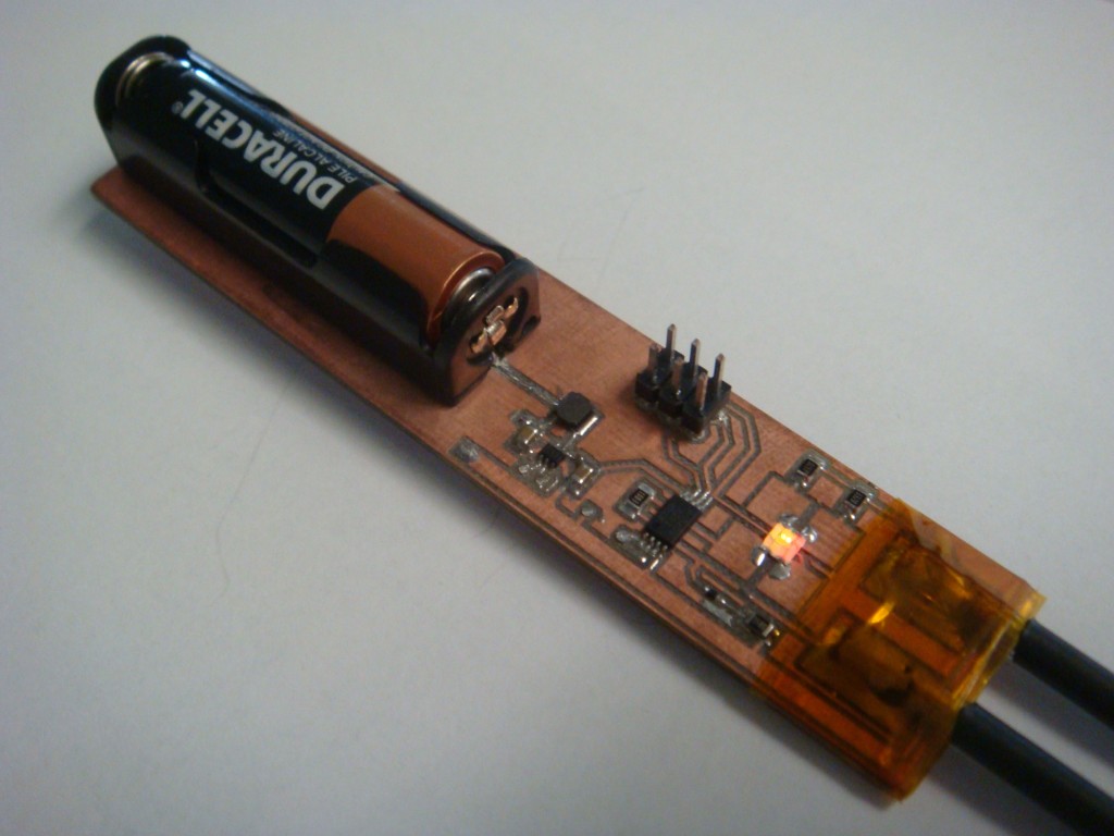
My wife suggested to me the idea of a visual indication for the soil moisture level in a houseplant (that is, before the brown leaves indication). We hadn’t seen anything like it in stores. So I made a prototype which worked quite nicely, and then we found that they were already available online through retailers like Amazon. Here’s the prototype I made:

It has two probes at one end that get inserted into the soil, and the LED then flashes either red, yellow, or green depending on the moisture content of the soil. It all runs on one AAA battery for about a month, but that could be improved by reducing the flash time and ADC sampling. The code for the prototype flashes the LED every second or two and samples every time.
11 Comments to Moisture Meter for Plants
Leave a Reply
Other Stuff
Recent Posts
- 6CY7 dual triode valve amplifier
- Air quality sensor (TVOC and eqCO2)
- Automotive rear fill “surround sound” with Boss DD-3
- Spring tester / weight scale
- Ducati 749/999 Tail Light
- Instruments for the GSXR
- Light pipe tail light for the GSXR
- M17x 6990m / 6970m overheating
- PAR / Spectrum analyzer
- Acrylic polishing and scratch removal
Archives
- May 2019 (2)
- April 2017 (3)
- October 2015 (1)
- May 2015 (1)
- March 2014 (2)
- December 2013 (1)
- July 2013 (1)
- November 2012 (1)
- October 2012 (4)
- September 2012 (1)
- August 2012 (3)
- June 2012 (1)
- March 2012 (1)
- February 2012 (1)
- January 2012 (1)
- October 2011 (3)
- July 2011 (1)
- June 2011 (3)
- May 2011 (2)
- April 2011 (1)
- December 2010 (1)
- August 2010 (1)
- July 2010 (3)
- April 2010 (2)
- March 2010 (2)
- January 2010 (2)
- December 2009 (2)
- October 2009 (2)
- September 2009 (1)
- August 2009 (15)
This seems like an interesting concept, do you have an explanation on the method used to measure the moisture content? What about the circuit/programs you developed?
I just used the fact that the soil will have some varying amount of conductivity based on the level of moisture in the system. Dry soil won’t conduct electricity, but wet soil will because of the high levels of impurities dissolved in the water by the soil. The circuit I made just checks the amount of conductivity of the soil at some interval, and then flashes an appropriate color LED.
How about you publish PCB files and schematics?
A possible better approach, would be to use a solar powered Cell, together with some kind of battery/accumulator (Capacitor ?) and then have a push button to trigger the test !
This way, no AAA batteries are required, and it still is simple to use.
Are you using ferrite rods, to stick into the soil ?
Hey, I like that. That would work really well. I didn’t think of putting a button on it to “check soil”, but using that approach you could omit the batteries completely. I may have to start playing with the new supercapacitors, as you suggested it would be perfect for this application.
The probes were just some small copper tubing that I tinned and then put heat shrink on.
Hi there, can you, please, supply the schematic diagram for this very interesting project?
thanks
Hi,
I can’t see what step-up regulator you are using in this project. Can you share the schematics with us? I am working on an “automatic blinds” and don’t have much room for the batteries there, so this booster IC would be just perfect for me!
Regards!
The step-up converter is TI’s TPS61221. It’s incredibly small at 2mm x 2mm, SC-70 6-pin package. I made the PCB on my CNC, but it was really at my machine’s limits.
It worked well, and seems pretty efficient at the load I was using (the AVR). You may want to select a different part depending on your load to get better efficiency. The curves for efficiency vs. current draw are given in the datasheet. They have a few different parts to match high efficiency with current draw.
I used the reference design from TI’s datasheet to make the schematic. There’s even a recommended layout. http://focus.ti.com/lit/ds/symlink/tps61221.pdf
I would like to talk to you, as I am working on a business plan for gardening tools manufacturing and your prototype approach as moisture meter is very interesting.
Pls. send me your phone number so I can explain to you with more detail the B.P.
Thank you.
Jaime, sorry I took so long to respond, I was sick for a while and then my wife and my son got sick as well. It’s been a little crazy.
You can send me an email to discuss things further, my email is on the “About Me” page. Thanks.
hi, I am working on a senior design where I have to build a moisture sensor that will interface with data acquisition device. I need to have a calibration of voltages that will be recorded during the day. The only battery is 3.3volts from the data acquisition device. The problem I am having is coming up with schematic that could work so that i could record several ranges of voltages. I think you design could help me and so I was wondering if you could send me the schematic or help me in some way.
Thank you very much.