mbed 1-wire EPROM driver (DS2502)
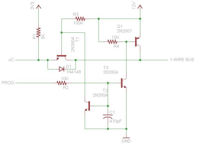
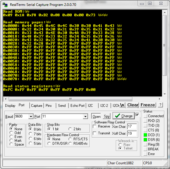
I wrote some code for my mbed to read and program the memory contents of 1-wire EPROMs like the DS2502. It should work with any device that responds to the same commands. The code can read ROM, status registers and memory pages, and write to the status register and memory pages. I also incorporated support for cyclical redundancy checks since the devices aren’t erasable. I had to build an external circuit for the 12 volt programming pulse to protect the mbed signal pin. If you only need to read you don’t need this, but it is required if you want to program data. Download link to the project source files is below.
1_Wire_Driver 2.95 KB
14 Comments to mbed 1-wire EPROM driver (DS2502)
Leave a Reply
Other Stuff
Recent Posts
- 6CY7 dual triode valve amplifier
- Air quality sensor (TVOC and eqCO2)
- Automotive rear fill “surround sound” with Boss DD-3
- Spring tester / weight scale
- Ducati 749/999 Tail Light
- Instruments for the GSXR
- Light pipe tail light for the GSXR
- M17x 6990m / 6970m overheating
- PAR / Spectrum analyzer
- Acrylic polishing and scratch removal
Archives
- May 2019 (2)
- April 2017 (3)
- October 2015 (1)
- May 2015 (1)
- March 2014 (2)
- December 2013 (1)
- July 2013 (1)
- November 2012 (1)
- October 2012 (4)
- September 2012 (1)
- August 2012 (3)
- June 2012 (1)
- March 2012 (1)
- February 2012 (1)
- January 2012 (1)
- October 2011 (3)
- July 2011 (1)
- June 2011 (3)
- May 2011 (2)
- April 2011 (1)
- December 2010 (1)
- August 2010 (1)
- July 2010 (3)
- April 2010 (2)
- March 2010 (2)
- January 2010 (2)
- December 2009 (2)
- October 2009 (2)
- September 2009 (1)
- August 2009 (15)


I have been building an alternate power supply for my M17x R4 with the projects you have posted here as a guide.
I reworked your mbed driver to work with my Arduino, and I have been able to successfully interrogate some DS2502 chips that I bought using your code. Thank you very much for posting it.
I would like to read the DS2502 from my current power adapter and write its memory to my new DS2502 chips to make the new power supply, but I have been unable to read it through the center pin of the power jack. I am hesitant to crack the case of the adapter to get to the chip because I should be able to get to it through the center pin (my laptop is doing this successfully after all). Are there any nuances to communicating with this chip while it is still in the adapter? I have tried various configurations of pull up resistors.
My next step is breaking out the oscilloscope and logic analyzer to see what is going on, but I figured I would ask you first since you have some experience.
Thanks in advance for any advice you might have.
The only thing I remember being critical was the timing since the devices are parasitically powered. Read a 1-wire PROM datasheet from maxim.
There is a bunch of other stuff hooked up to that center pin. Make sure to check your logic high voltage is what it’s supposed to be, and not being loaded down. Also make sure you are properly pulling the line low, you may need to drive it both directions. Since there is other stuff on that line you can’t assume a pull-up or pull-down will work. I remember the 330W PS being much harder to ID than the 240W version. There is also a zener that prevents programming pulses, but I don’t know what voltage it is rated at so maybe try a slightly lower voltage if you are running it at the high end of the voltage range.
And yeah nothing substitutes breaking out the oscilloscope. It’s been quite a while, but that’s what I remember about it. Good luck!
Just a quick update. I was unfortunately not able to access my power adapter EPROM through its center pin, but I did manage to find out why and I though I would share:
After troubleshooting I found a few interesting things. The computer holds the line high at 3V with its master side pull up resistor (no surprise there) The interesting bit is that the computer pulses the line to 5V (the highest voltage the data line ever sees) three times in quick succession about .3ms between pulses, then holds the line low for one full second after you connect it to the adapter. I can only guess this bypasses an internal circuit to allow normal access to the 1-Wire memory because it is no where in the 1-wire protocol.
The end result is that I was able to pull my full EPROM memory off of the chip while my computer was connected. Now its on the the next step; copying the data to the new memory chip and testing it out.
The real question is going to be: with the new memory chip in a separate adapter, will the computer recognize it as valid or is there more communication required to validate the power supply?
Nice work Jeremy! Is this with a 240W or 330W supply? It would be interesting to see if you got a different sequence when using the two different adapters. I remember using a logic analyzer to snoop the 1-wire line when plugging it into the motherboard, but I never used a scope to see voltage levels.
I think you will be okay with your own PS as long as you are using the 240W EPROM data. Actually I bet you could get away with just programming “240” at the same location. There was speculation that the motherboard did some other tricks with the power supply when the 330W supply wasn’t working, but that was cleared up by tricking the 330W PS. There appears to be current sensing capability on the motherboard but it doesn’t appear to be used to validate the supply.
The power supply I am using is my stock 240W power supply. Here is my full EPROM memory data for anyone that wants to use it for future tinkering:
Read memory pages:
0x0000 0x44 0x45 0x4C 0x4C 0x30 0x30 0x41 0x43
0x0008 0x32 0x34 0x30 0x31 0x39 0x35 0x31 0x32
0x0010 0x33 0x43 0x4E 0x30 0x46 0x57 0x43 0x52
0x0018 0x43 0x34 0x38 0x36 0x36 0x31 0x32 0x41
0x0020 0x56 0x32 0x35 0x38 0x43 0x41 0x30 0x32
0x0028 0x6B 0xCA 0xFF 0xFF 0xFF 0xFF 0xFF 0xFF
0x0030 0xFF 0xFF 0xFF 0xFF 0xFF 0xFF 0xFF 0xFF
0x0038 0xFF 0xFF 0xFF 0xFF 0xFF 0xFF 0xFF 0xFF
0x0040 0xFF 0xFF 0xFF 0xFF 0xFF 0xFF 0xFF 0xFF
0x0048 0xFF 0xFF 0xFF 0xFF 0xFF 0xFF 0xFF 0xFF
0x0050 0xFF 0xFF 0xFF 0xFF 0xFF 0xFF 0xFF 0xFF
0x0058 0xFF 0xFF 0xFF 0xFF 0xFF 0xFF 0xFF 0xFF
0x0060 0xFF 0xFF 0xFF 0xFF 0xFF 0xFF 0xFF 0xFF
0x0068 0xFF 0xFF 0xFF 0xFF 0xFF 0xFF 0xFF 0xFF
0x0070 0xFF 0xFF 0xFF 0xFF 0xFF 0xFF 0xFF 0xFF
0x0078 0xFF 0xFF 0xFF 0xFF 0xFF 0xFF 0xFF 0xFF
CRC OK: 0xCC
Another update on the quest for a non-dell power adatper:
I finally received the adapter plug for the M17xR4 from china. It cost me 5$ including shipping from ebay. I was able to test the DS2502 that I have programmed. After a brief failure involving a leg of the DS2502 tearing off, I programmed a new one and installed it in the adapter plug with the data and power leads soldered to the data line and the ground lead soldered to the negative voltage line.
I connected the leads of the adapter plug to a variable power supply and set it to 19.5 volts and maximum current. The immediately recognized the new power source as a valid 240W adapter. Success!!!
The laptop drew steadily more current from the DC power supply I had it hooked up to. It began at about .6A and drew .4A more every second until…. The DC power supply I was using hit its limit and its voltage dropped down. After the voltage drop the laptop gave an incorrect adapter error. I will be building a new power supply soon to more thoroughly test the idea.
If I were to guess, I think that the DS2502 should work to make the laptop recognize that it is a valid power adapter (and stay that way) if I can get a power source to put out more current at the rated voltage. I will post an update after I build the new power supply.
Hi Jeremy,
Would you be willing to share your ‘Arduinoised’ version of Josh’s library?
In the driver circuit, what is PROG connected to ? uC is connected to the microcontroller singal and 3V3 to 3.3 V, but I am not sure where I should connect PROG to.
I am building the circuit for programming one wire devices. Is the circuit different for different microcontrollers ?
@Jeremy, I would love to do the same with my Dell Adapter, do you still have the code/hardware config required for conversion of an ordinary adapter into a dell one?
Thanks for the help,
Rohin G
For Josh,
In your “mbed 1-wire EPROM driver (DS2502)”, you write : “Download link to the project source files is below.”, but I don’t find 🙁
Can you send me link to your project ? I’m very interesting.
For Jeremy,
You say “I reworked your mbed driver to work with my Arduino”, can you share your job ?
Thanks by advance for your attention !
Tshaad.
uc pin is programmers data output right? what is prog pin?
i just build circuit waiting answers guys
thanks in advance
Sorry everyone, the download manager deleted the package, I’ve fixed it and hopefully it stays up now.
Can you list the devices you used to do the programming? I am trying to make a solution to charge multiple Dell laptops off one variable power supply through adapters.
I used an NXP LPC1768 mbed.